Sunuyu indir
Sunum yükleniyor. Lütfen bekleyiniz

3
Funnel Navigation Bridge Superstructure Hatch Deck Crane

4
Superstructure Port Side Stern Deck Bow Starboard Side

5
Poop Deck MainDeck Forecastle Deck

8
Basic Ship Theory, Vol 1, page: 8

9
THREE DIMENSIONAL HULL FORM

10
Transverse Section

11
Transverse Section

12
Stations

13
Body Plan

14
Horizontal Section

15
Waterline

16
Waterlines

17
Plan View

18
Vettical Sections

19
Buttocks

20
Buttocks

21
Profile View

22
Lines Plan

23
Offset Table

24
Cross Sectional Areas

25
GEOMETRIC DEFINITIONS
SHIP GEOMETRY

26
4.1 GEOMETRIC DEFINITIONS
AP FP BL D LWL LOA LBP f B B/2 Deck Loaded waterline Figure 4.1. General geometric definitions

27
STANDARD DEFINITIONS OF LENGTH

28
STANDARD DEFINITIONS OF LENGTH

29
Fore Perpendiculars (FP) : A line drawn perpendicular to the waterline at the point where the forward edge of the stem intersects the summer load line. Aft Perpendiculars (AP) : A line perpendicular to the waterline either (1) where aft edge of the rudder post meets the summer load line or (2) in cases where no rudder post is fitted, the centerline of the rudder pintles is taken . Midships The point midway between the forward and after perpendiculars . Centreplane (CL) : It is a referance plan that divide the ship in longitudinal direction in the mid point of beam between port and starboard sides. Baseline (BL) : A fore-and-aft reference line at the upper surface of the flat plate keel at the centerline for flush shell-plated. Vertical dimensions are measured from a horizontal plane through the baseline, often called the molded baseline. Midship Section : The section of the ship at this point by a plane normal to both the summer waterplane and the centreline plane of the ship is called the midship section. It may not be the largest section of the ship. Unless otherwise defined the beam is usually quoted at amidships. Sheer Line the curvature of the deck in a longitudinal direction. It is measured between the deck height at midships and the particular point along the deck.
 : A line perpendicular to the waterline either (1) where aft edge of the rudder post meets the summer load line or (2) in cases where no rudder post is fitted, the centerline of the rudder pintles is taken . Midships The point midway between the forward and after perpendiculars. . Centreplane (CL) : It is a referance plan that divide the ship in longitudinal direction in the mid point of beam between port and starboard sides. Baseline (BL) : A fore-and-aft reference line at the upper surface of the flat plate keel at the centerline for flush shell-plated. Vertical dimensions are measured from a horizontal plane through the baseline, often called the molded baseline. Midship Section : The section of the ship at this point by a plane normal to both. the summer waterplane and the centreline plane of the ship is called the midship section. It may not be the largest section of the ship. Unless otherwise defined the beam is usually quoted at amidships. Sheer Line the curvature of the deck in a longitudinal direction. It is measured between the deck height at midships and the particular point along the deck.")
30
Şekil 4.2. Trimsiz ve trimli durum
Deck Camber : The rise or crown of a deck, athlwartship; also called round of beam. It can be 1/50 times of beam as a standard value. Parallel Body (LP) : The amidship portion of a ship with in which the contour of the under water hull form is unchanged. Siyer Baş Kıç BL LWL BL LWL Şekil 4.2. Trimsiz ve trimli durum
 : The amidship portion of a ship with in which the contour of the under water hull form is unchanged. Siyer. Baş. Kıç. BL. LWL. BL. LWL. Şekil 4.2. Trimsiz ve trimli durum.")
31
sintine dönümü radius güverte sehimi tumblehome f T kalkıntı
levha omurga LWL BL CL Şekil 4.3. Enine kesit karakteristikleri

32
Şekil 4.4. Section lines

33
Figure 4.5Bulbousbow area definition figure
Bulbous bow area (ABL) : Bulbous area at center plane. Bulbous bow section area (ABT) : Bulbous bow area at fore perpendicular. FP ABL ABT Figure 4.5Bulbousbow area definition figure
 : Bulbous area at center plane. Bulbous bow section area (ABT) : Bulbous bow area at fore perpendicular. FP. ABL. ABT. Figure 4.5Bulbousbow area definition figure.")
34
Main Dimensions Length Overall (LOA) - Tam Boy : The distance between extreme points of the ship forward and aft. Length Between Perpendiculars (LBP) - Dikmeler Arası Boy : Distance between fore and aft perpendiculars. Length of Waterline (LWL) - Su Hattı Boyu : Distance between Geminin dizayn su hattında yüzerken başta ve kıçta su ile temas eden en uç noktaları arasındaki yatay uzaklıktır. Length Overall Submerged (LOS) - Batık Boy: Geminin dizayn su hattı altında kalan kısmında başta ve kıçta en uç noktalar arasındaki yatay uzaklık olup yumrubaşlı gemilerde önem kazanan bir boy değeridir. Parallel Body Length (LP) - Paralel Gövde Boyu : Gemi ortasında orta kesidin hiçbir değişikliğe uğramadan uzandığı bölge boyu. Draught (T) - Su Çekimi The draft is vertical distances from the base line to the waterline of reference measured at the forward and after perpendiculars respectively. The molded draft is measured from the molded base line.
 - Dikmeler Arası Boy : Distance between fore and aft perpendiculars. Length of Waterline (LWL) - Su Hattı Boyu : Distance between Geminin dizayn su hattında yüzerken başta ve kıçta su ile temas eden en uç noktaları arasındaki yatay uzaklıktır. Length Overall Submerged (LOS) - Batık Boy: Geminin dizayn su hattı altında kalan kısmında başta ve kıçta en uç noktalar arasındaki yatay uzaklık olup yumrubaşlı gemilerde önem kazanan bir boy değeridir. Parallel Body Length (LP) - Paralel Gövde Boyu : Gemi ortasında orta kesidin hiçbir değişikliğe uğramadan uzandığı bölge boyu. Draught (T) - Su Çekimi The draft is vertical distances from the base line to the waterline of reference measured at the forward and after perpendiculars respectively. The molded draft is measured from the molded base line.")
35
Moulded Breadth (BM) : Geminin en geniş kesidinde sancak ve iskele bordalar arasındaki yatay uzaklıktır. Breadth of Waterline (BWL) : Geminin yüzdüğü su hattında ve en geniş kesidinde sancak ve iskele bordalar arasındaki yatay uzaklıktır. Depth (D) : The vertical distance between the base line and the upper continuous deck. The depth is measured at half LBP at the side of the ship. Freeboard (f) : the vertical distance from the summer load waterline to the top of the freeboard deck plating, möeasured at the ship’s side amidshipsthe upprmost complete deck exposed to the weather and sea is normally the freeboard deck. Flare . The outward curvature of the side shell at the forward end above th ewaterline Rake: a line in profile inclined from the vertical, indicating for instance the shape of stem. Flat of keel : the width of the horizontal portion of the bottom shell in the region of the upper deck Bilge Radius : the radius of the plating joining the side shell to the bottom of shell. Thumbledome: an inward curvature of the midship side shell in the region of the upper deck Rise of Floor : the height of the bottom shell plating above the baseline
 : Geminin yüzdüğü su hattında ve en geniş kesidinde sancak ve iskele bordalar arasındaki yatay uzaklıktır. Depth (D) : The vertical distance between the base line and the upper continuous deck. The depth is measured at half LBP at the side of the ship. Freeboard (f) : the vertical distance from the summer load waterline to the top of the freeboard deck plating, möeasured at the ship’s side amidshipsthe upprmost complete deck exposed to the weather and sea is normally the freeboard deck. Flare . The outward curvature of the side shell at the forward end above th ewaterline. Rake: a line in profile inclined from the vertical, indicating for instance the shape of stem. Flat of keel : the width of the horizontal portion of the bottom shell in the region of the upper deck. Bilge Radius : the radius of the plating joining the side shell to the bottom of shell. Thumbledome: an inward curvature of the midship side shell in the region of the upper deck. Rise of Floor : the height of the bottom shell plating above the baseline.")
36
4.3. Hull Form and Form Coefficients
Bir geminin: inşa ve işletim maliyetleri, taşıma kapasitesi, yerleşim özellikleri, sevk karakteristikleri, hız, stabilite, enine ve boyuna mukavemet ve yapısal dizayn özellikleri gibi temel tekno-ekonomik performans karakteristiklerini etkileyen en önemli elemanı tekne boyutları ve formudur.

37
4.3. Tekne Formu ve Form Katsayıları
Üç boyutlu tekne formunu iki boyutlu kağıt düzlemine aktarabilmek üzere form veya endaze planı denilen üç adet iki boyutlu düzlemden oluşan bir plandan yararlanılır. Form planını oluşturan iki boyutlu düzlemler şunlardır: Geminin boy yönünde orta keside paralel kesitlerle bölünmesi ile elde edilen enkesit planı Geminin düşey yönde yüklü su hattına paralel kesitlerle bölünmesi ile elde edilen su hatları planı Geminin iskele veya sancak yönünde orta simetri düzlemine paralel kesitlerle bölünmesi ile elde edilen batok eğrileri ve profil planı.

38
TEKNE FORMU Üç boyutlu düzgünlüğe sahip bir tekne formuna ait her üç plandaki iki boyutlu eğriler de düzgün olacaktır. Form planında herbir su hattı, batok ve enkesit için tek bir kesim noktası bulunabileceğine göre bu kesim noktasının temel hattına, orta simetri düzlemine ve gemi ortasına uzaklıkları her üç planda da aynı olmalıdır. Bu durum Şekil 4.6’ da gösterilmektedir. Tekne form eğrilerinin çiziminde elastik tirizler kullanılır. Bu tirizler üstlerine konan ağırlıkların etkisi altında potansiyel enerjilerini minimum yapacak sürekli bir form alırlar. İdeal olarak eğri üzerinde koordinatları bilinen herbir nokta üzerine bir ağırlık konmalıdır. Eldeki ofset sayısının fazla olması eğrilerin daha duyarlı olarak çizilmesini sağlayacaktır. Genellikle kesit sayısı 21’den, su hattı sayısı 6’dan ve batok sayısı 4’den az olmayacak şekilde seçilir.

39
TEKNE FORMU Çok özel haller dışında gemi tekne formlarında sancak-iskele simetrisi bulunduğundan enkesit ve su hattı planlarında sadece iskele veya sancak taraf çizilir. Geleneksel olarak enkesit planında gemi ortasından başa doğru olan kesitler sağa, gemi ortasından kıça doğru kesitler ise sol tarafa çizilir. Su hattı planında ise sadece iskele su hatları çizilir. Gemi formunu tanımlamak üzere baş ve kıç dikeyler arası belirli sayıda aralığa bölünür (tipik 20 aralık). Gemi formunun hızlı değişim gösterdiği baş ve kıç nihayetlerde ara kesitler alınması yaygındır. Herbir keside ait su hattı yarı genişlikleri ofset değeri olarak adlandırılır ve bu değerlerle gemi tekne formunu tanımlayan bir ofset tablosu oluşturulur. Tipik bir balıkçı gemisine ait form planı Şekil 4.7’de görülmektedir.
. Gemi formunun hızlı değişim gösterdiği baş ve kıç nihayetlerde ara kesitler alınması yaygındır. Herbir keside ait su hattı yarı genişlikleri ofset değeri olarak adlandırılır ve bu değerlerle gemi tekne formunu tanımlayan bir ofset tablosu oluşturulur. Tipik bir balıkçı gemisine ait form planı Şekil 4.7’de görülmektedir.")
40
Şekil4.6. Üç boyutlu tekne formu ve kesit düzlemleri
Batoklar Su hatları En kesitler Z X Y Şekil4.6. Üç boyutlu tekne formu ve kesit düzlemleri

41
Table 4.1. Typical offset table
İst Yarı Genişlikler Main Deck Küpeşte BL 0 m WL1/2 0.5 m WL 1 1 m WL 2 2 m WL 3 3 m WL m WL 5 5 m WL 6 6 m Yükseklik Yarı Genişlik Ayna - 2140 6650 7550 5700 7350 9450 3260 6900 7710 7540 600 4250 7170 7820 7700 1 300 2280 5120 7400 7880 7810 2 1620 4630 6440 7730 7900 3 1580 3820 3830 6170 7280 7870 4 370 1740 3200 5500 7120 5 860 3140 4700 6620 7620 6 2120 4730 5920 7270 7 3780 5900 6720 7580 8 4900 6390 7100 7895 9 5070 6400 7080 7720 7890 10 6880 7570 7840 11 4000 5680 6450 7240 7860 7830 12 3130 4990 5820 6700 7250 7800 7850 13 2230 4230 5040 6000 7000 7480 7750 7670 14 1400 3500 4220 5770 6250 6950 7430 5724 7300 9474 15 750 2730 3380 4180 4800 5320 6180 5753 6730 9503 16 330 1990 2530 3220 4280 5250 6225 5783 9536 17 130 1380 1830 2400 2850 4150 5812 5100 9575 18 60 920 1320 1730 1960 2170 2930 4190 5841 3970 9623 19 40 550 900 1290 1250 1140 1650 2790 5870 2650 9682 6410 19 ½ 380 700 1090 1050 610 970 2000 5885 1920 9715 5810 20 280 530 1000 320 1220 9748 5090

42
Figure 4.7. A typical lines plan

43
Form Coefficients

44
Midship Section Coefficient

45
Waterplane Area Coefficient

46
Block Coefficient L*B*T

47
Prismatic Coefficient

48
-Displacement /Length Ratio

49
BLOCK COEFICIENT CB

50
WATERPLANE AREA COEFICIENT (CWP)
.

51
midships section coefficient (CM)
")
52
PRISMATIC COEFICIENT (CP)
")
53
Vertical prisMAtic coefficient (CVP)
")
54
Example 4.6. Find the form coefficients of a 100 m long barge with corss section as given below. 10m 1m 1.5m Midship cross section Area : Midship cross section area coefficient : Displacement Volume :

55
Block coefficient : Prizmatic coefficient : Waterplane area coefficient:

56
Midship section coefficient :
Örnek 4.3. Find the form coefficients of a a barge with cross section as given below. 5m Blok coefficient : Midship section coefficient :

57
Prizmatic coefficient :
Waterplane area coefficient: Vertical prizmatic coefficient:

58
Midship Section coefficient :
Example 4.1. Find the form coefficients of a cylinderical barge with length of L and radius of R with cross section as given below R Block Coefficent : Midship Section coefficient : Prizmatic coefficient :

59
Waterplane area coefficient:
Vertical prizmatic coefficient

60
Midship section coefficient :
Example 4.2 Calculate form coeffcients of the barge with length L with cross section as below. R R 4R Block coefficient : Midship section coefficient : Prizmatic coefficient:

61
Waterplane area coefficient
Vertical prizmatic coefficent

62
Midship section coefficient :
Örnek 4.4. Aşağıda profil kesiti verilen ve bir dairesel silindir ve koniden oluşan dubanın orta simetri ekseni su hattı olacak şekilde yüzmesi durumunda form katsayılarını hesaplayın. r H Block coefficient : Midship section coefficient :

63
Prismatic coefficient
Waterplane area coefficient Vertical prismatic coefficient Longitudinal center of floation Longitudinal center of bouyancy

64
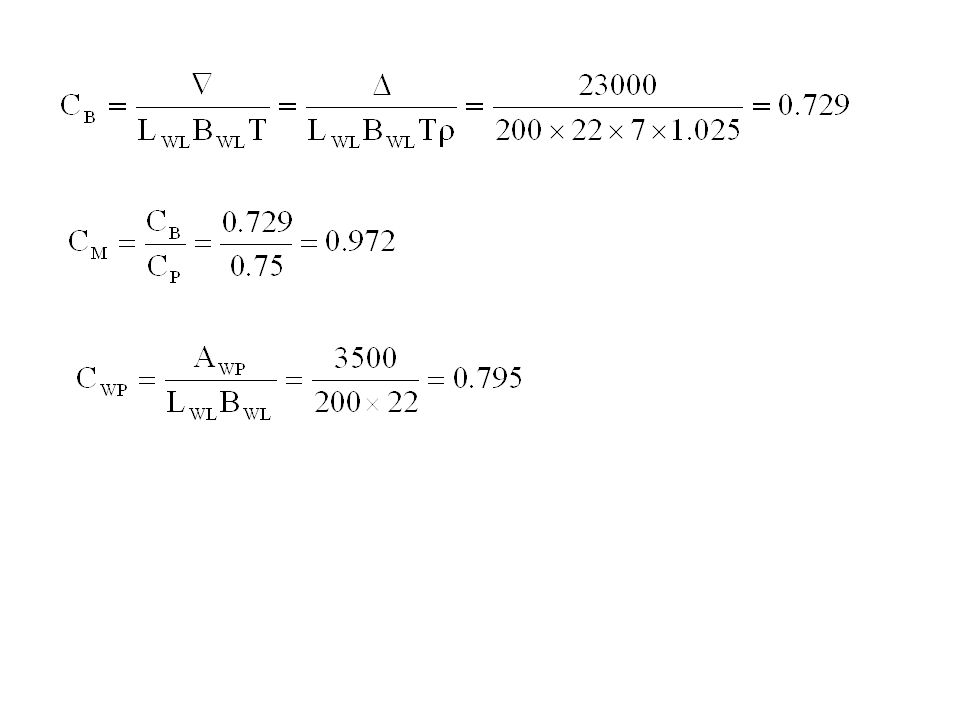
Prizmatic coefficient CP 0.75
Example 4.5. Calculate the form coefficients for a ship with the following characteristics. Waterline length LWL 200 m Waterline breadth BWL 22 m Draught T 7 m Prizmatic coefficient CP 0.75 Loaded waterplane area AWL 3500 m2 Displacement tonnage 23000 t Sea water density 1.025 t/m3

Benzer bir sunumlar


 Sistemlerin Frekans Tepkileri>")
 MOMENTİ>")


>")
 Köprüüstü (Navigation Bridge) Üstyapı (Superstructure) Hatch Güverte (Deck:)) Kreyn (Crane)>")


 Gemi mühendisliğinde, bir gemi formunun kağıt üzerinde belirli bir ölçekle, teknik resim kuralları yardımıyla gösterilmesine.>")


>")
