Sunuyu indir
Sunum yükleniyor. Lütfen bekleyiniz

1
İNCE CİDARLI TÜPLERİN BURULMASI THIN-WALLED TUBES
Kapalı tüpler

2
Dairesel kesitli-ince cidarlı tüplerin burulması
İnce cidarlı ve kapalı tüplerin burulma problemleri, Coulomb teorileri ile çözülebilen dairesel tüplerden elde edilen sonuçlardan yararlanarak elemanter olarak çözülebilmektedir. Ortalama yarıçap Cidar kalınlığı

3
1) Daire kesitli tüpler: İçi boş daire kesitli millerin burulması dikkate alınarak ince cidarlı tüplerin burulma formülleri çıkarılabilir. İçi boş dairesel kesitlerde maksimum kayma gerilmesi kesitin dış yüzeyine yakın noktalarda meydana gelir: (a) İnce cidarlı dairesel kesitlerde ortalama kayma gerilmesi cidar boyunca sabit kabul edilir ve aşağıdaki gibi hesaplanır: (b)
 İnce cidarlı dairesel kesitlerde ortalama kayma gerilmesi cidar boyunca sabit kabul edilir ve aşağıdaki gibi hesaplanır: (b)")
4
İçi boş milin polar atalet momenti:
İçi boş dairesel kesitin dış ve iç yarıçapları kullanılarak aşağıdaki gibi bulunur: Dairesel tüplerin polar atalet momenti: Yukarıdaki polar atalet momenti ifadesi aşağıdaki gibi çarpanlara ayrılır: (a) burada şeklindedir. Buna göre polar atalet momenti aşağıdaki gibi olur: (b)
 burada. şeklindedir. Buna göre polar atalet momenti aşağıdaki gibi olur: (b)")
5
t cidar kalınlığı R ortalama yarıçapı yanında çok küçükse J=2πR3t=2ARt polar atalet momenti kullanılabilir. (b) şeklinde görüldüğü gibi ince cidarlı tüplerde cidar kalınlığı boyunca kayma gerilmelerinin değişmediği kabul edilebilir. Bu durumda Birim dönme açısı ise: burada s ortalama çevre uzunluğudur. Buna göre tüpün toplam dönme açısı aşağıdaki gibi olur:

6
Örnek: Şekildeki dairesel kesitli mil T=6 kNm’lik bir burulma momentine maruz bırakıldığına göre meydana gelen kayma gerilmesini ve birim dönme açısını hesaplayınız (G=25 GPa). Dış ve iç çaplar sırası ile D=128 mm ve d=122 mm olarak verilmektedir. d D T=6 kNm

7
Ortalama çap ve cidar kalınlığı:
Kesit özellikleri (Alan ve Polar atalet momenti): veya
: veya.")
8
Cidarda oluşan ortalama kayma gerilmesi:
veya Birim dönme (burulma) açısı:
 açısı:")
9
İçi boş mil durumuna göre kayma gerilmesi ve birim dönme açısı:

10
FIG. 3-40 Thin-walled tube of arbitrary cross-sectional shape
Non-circular Thin-Walled Hollow Shafts The stresses acting on the longitudinal faces a-b and cd produce forces Fb and Fc (Fig. 3-40d). These forces are obtained by multiplying the stresses by the areas on which they act: in which tb and tc represent the thicknesses of the tube at points b and c, respectively (Fig. 3-40d). FIG Thin-walled tube of arbitrary cross-sectional shape
. These forces are obtained by multiplying the stresses by the areas on which they act: in which tb and tc represent the thicknesses of the tube at points b and c, respectively (Fig. 3-40d). FIG Thin-walled tube of arbitrary cross-sectional shape.")
11
FIG. 3-40 Thin-walled tube of arbitrary cross-sectional shape
In addition, forces F1 and F1 are produced by the stresses acting on faces b-c and a-d. From the equilibrium of the element in the longitudinal direction (the x direction), we see that Fb = Fc , or
, we see that Fb = Fc , or.")
12
Kayma Akımı (Shear Flow)
Because the locations of the longitudinal cuts a-b and c-d were selected arbitrarily, it follows from the preceding equation that the product of the shear stress τ and the thickness t of the tube is the same at every point in the cross section. This product is known as the shear flow and is denoted by the letter q: or (3-59)
")
13
This relationship shows that the largest shear stress occurs where the thickness of the tube is smallest, and vice versa. Naturally, in regions where the thickness is constant, the shear stress is constant. Note that shear flow is the shear force per unit distance along the cross section.

14
FIG. 3-41 Cross section of thin-walled tube
İnce cidarlı tüplerde burulma formülü (Torsion Formula for Thin-Walled Tubes) The next step in the analysis is to relate the shear flow q (and hence the shear stress τ) to the torque T acting on the tube. For that purpose, let us examine the cross-section of the tube, as pictured in Fig FIG Cross section of thin-walled tube median line r
 The next step in the analysis is to relate the shear flow q (and hence the shear stress τ) to the torque T acting on the tube. For that purpose, let us examine the cross-section of the tube, as pictured in Fig FIG Cross section of thin-walled tube. median line. r.")
15
The median line (also called the centerline or the midline) of the wall of the tube is shown as a dashed line in the figure. We consider an element of area of length ds (measured along the median line) and thickness t. The distance s defining the location of the element is measured along the median line from some arbitrarily chosen reference point.
 and thickness t. The distance s defining the location of the element is measured along the median line from some arbitrarily chosen reference point.")
16
FIG. 3-41 Cross section of thin-walled tube
The total shear force acting on the element of area is qds, and the moment of this force about any point O within the tube is FIG Cross section of thin-walled tube median line r in which r is the perpendicular distance from point O to the line of action of the force qds. The total torque T produced by the shear stresses is obtained by integrating along the median line of the cross section: in which Lm denotes the length of the median line.

17
The integral above can be difficult to integrate by formal mathematical means, but fortunately it can be evaluated easily by giving it a simple geometric interpretation. The quantity rds represents twice the area of the shaded triangle shown in Fig (Note that the triangle has base length ds and height equal to r.)
")
18
Therefore, the integral represents twice the area Am enclosed by the median line of the cross section: Therefore the shear flow is Now we can obtain a torsion shear formula for thin-walled tubes:

19
Dairesel olmayan ince cidarlı tüplerin burulması
2) Herhangi bir biçimdeki tüp kesitli çubuklar: Şekil (a) da görüldüğü gibi herhangi bir kesiti olan çubuk dikkate alalım. Bu çubuktan çok küçük parçayı büyütüp dengesini inceleyelim. Bu eleman dengede olduğundan, örnek olarak karşılıklı kesitlerde bulunan V3 ve V4 kesme kuvvetleri de dengededir. ve olur. Kayma gerilmesi cidar kalınlığı çarpımına kayma akımı denir ve q ile gösterilir.
 Herhangi bir biçimdeki tüp kesitli çubuklar: Şekil (a) da görüldüğü gibi herhangi bir kesiti olan çubuk dikkate alalım. Bu çubuktan çok küçük parçayı büyütüp dengesini inceleyelim. Bu eleman dengede olduğundan, örnek olarak karşılıklı kesitlerde bulunan V3 ve V4 kesme kuvvetleri de dengededir. ve olur. Kayma gerilmesi cidar kalınlığı çarpımına kayma akımı denir ve q ile gösterilir.")
20
Dik köşelerde, yani birbirine dik kesitlerde kayma gerilmelerinin eşit olması şartından
yazılabilir. Buna göre kayma akımları Cidar eksen eğrisi s üzerinde alınan (t ds) alan elemanına etkiyen dV kesme kuvveti veya şeklindedir.
 alan elemanına etkiyen dV kesme kuvveti. veya. şeklindedir.")
21
Tüplerde Kayma Gerilmesinin Bulunması
Kesit eğrisi boyunca kayma akımlarının eşit olması (q1=q2=q3=…) şartından dV kesme kuvvetinin büyüklüğü de sabit kalır. Bu kesme kuvvetinin kesit düzlemi içerisindeki herhangi bir O noktasına göre momenti, kesite etkiyen T burulma momentine eşit olmalıdır. Bu durumda yazılır. veya
 şartından dV kesme kuvvetinin büyüklüğü de sabit kalır. Bu kesme kuvvetinin kesit düzlemi içerisindeki herhangi bir O noktasına göre momenti, kesite etkiyen T burulma momentine eşit olmalıdır. Bu durumda. yazılır. veya.")
22
İntegral içindeki (h ds) terimi, şekildeki taralı üçgen (dA) alanının iki katıdır. Buna göre burulma momenti şeklinde olur. Burulma momenti ifadesinden kayma gerilmesi çekilirse aşağıdaki gibi olur:

23
Buna göre kesitteki en büyük kayma gerilmesi, cidar kalınlığının en küçük olduğu noktada meydana geleceği açıktır. Bu durumda maksimum kayma gerilmesi A gibi olur. Burada A kesit cidar orta hattının sınırladığı alandır.

24
Tüplerde Burulma Açısının Bulunması
Kesitin θ birim dönme açısını hesaplamak için şekil değiştirme enerjisinde yararlanılabilir. T burulma momentinin yaptığı iş, dφ= θ dz olduğu bilinerek şeklinde olur. dz boyundaki parçada biriken enerji, τ/2G enerji yoğunluğu kullanılarak şeklinde olur. Burada, τ kayma gerilmesi, G kayma modülü ve dV hacim elemanıdır.

25
Yukarıdaki iş ve enerji ifadesi birbirine eşitlenirse
(burada ) elde edilir. Burada dV hacim elemanı olup dV=t ds dz yukarıdaki denklemde yerine konulursa elde edilir. Bu ifade düzenlenirse tüpün birim dönme (burulma) açısı aşağıdaki gibi olur:
 elde edilir. Burada dV hacim elemanı olup dV=t ds dz yukarıdaki denklemde yerine konulursa. elde edilir. Bu ifade düzenlenirse tüpün birim dönme (burulma) açısı aşağıdaki gibi olur:")
26
Thin-Walled Hollow Shafts
Summing forces in the x-direction on AB, shear stress varies inversely with thickness Compute the shaft torque from the integral of the moments due to shear stress Angle of twist (from Chapt 11)
")
27
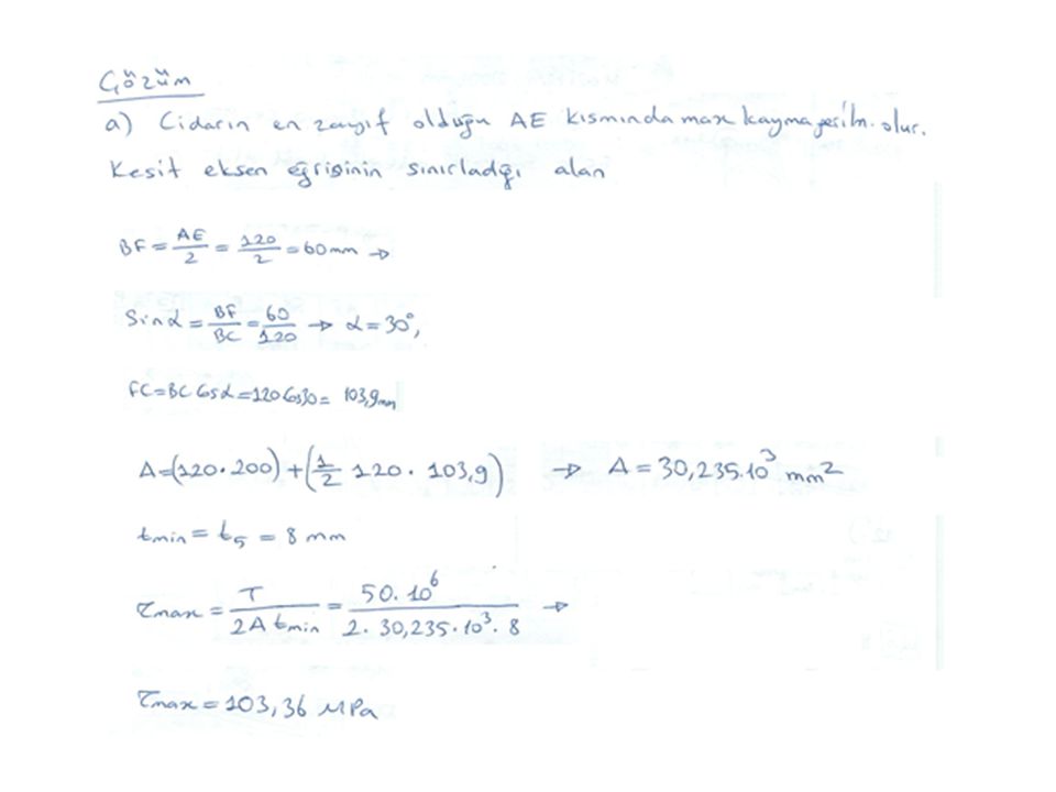
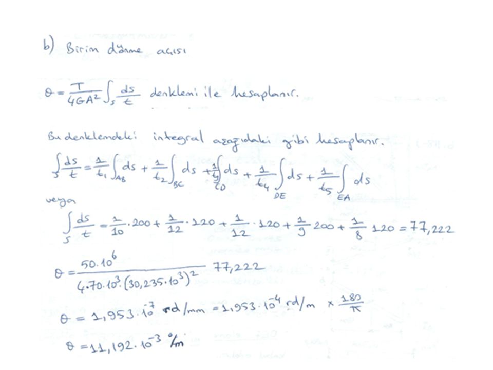
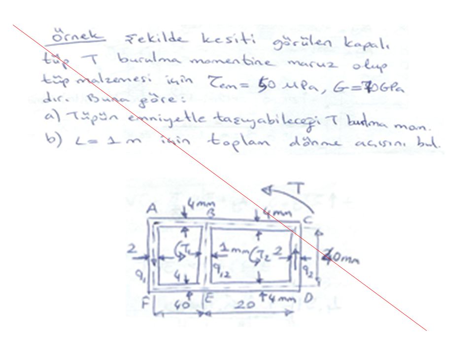
Örnek: Boyutları şekilde verilen tüp, T=50 kNm’lik burulma momentine maruz bırakılıyor. Buna göre:
Kesitte meydana gelen en büyük kayma gerilmesini ve yerini bulunuz. Birim dönme açısını hesaplayınız (G=70 GPa)
")
30
Example 3.10 Extruded aluminum tubing with a rectangular cross-section has a torque loading of 24 kip-in. Determine the shearing stress in each of the four walls with uniform wall thickness of in. and wall thicknesses of 0.120 in. on AB and CD and in. on CD and BD.

31
SOLUTION: Determine the shear flow through the tubing walls Find the corresponding shearing stress with each wall thickness

32
SOLUTION: Determine the shear flow through the tubing walls

33
with a variable wall thickness
Find the corresponding shearing stress with each wall thickness with a uniform wall thickness, with a variable wall thickness

34
İnce Cidarlı Tüplerin Burulması
Various thin-walled members

35
Torsion of circular and rectangular members

36
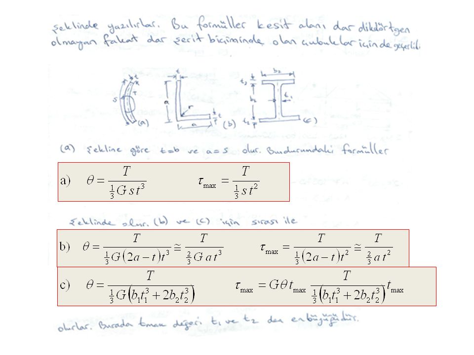
Dikdörtgen kesitli miller Açık tüpler

37
Torsion of Noncircular Members
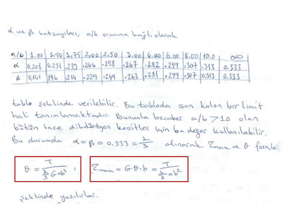
Circular torsion formulas are not valid for non-circular shafts. Planar cross-sections of noncircular shafts do not remain planar and stress and strain distribution do not vary linearly For uniform rectangular cross-sections,

38
At large values of a/b, the maximum shear stress and angle of twist for other open sections are the same as a rectangular bar.

45
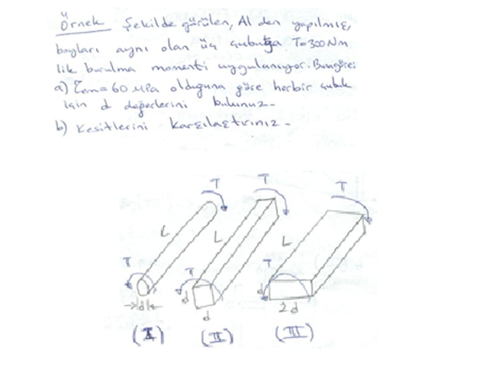
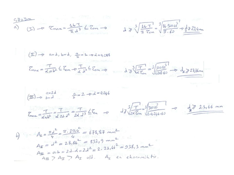
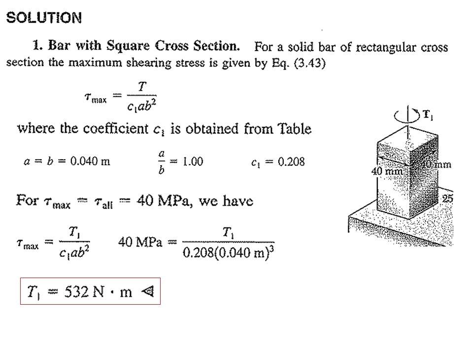
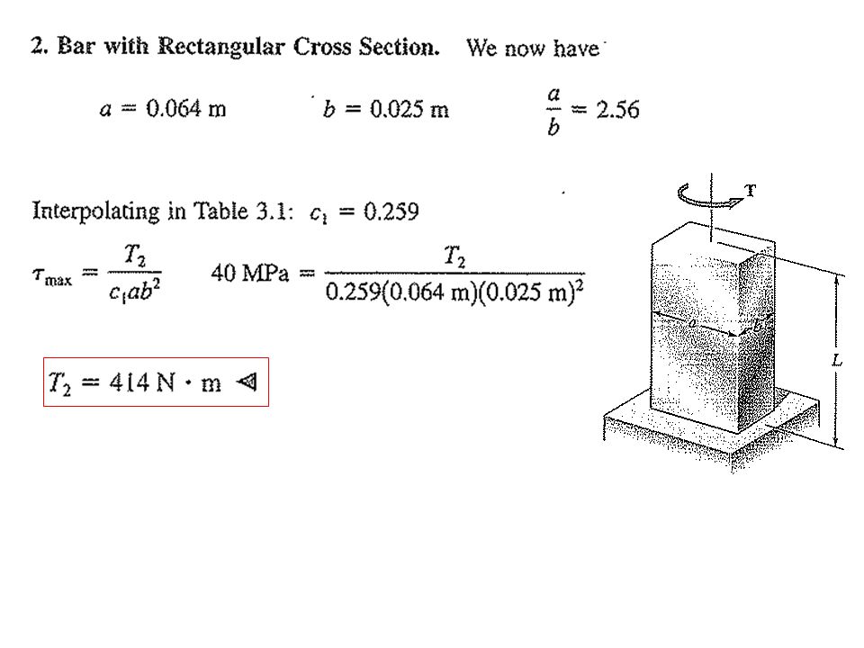
SAMPLE PROBLEM 3.9 Using τall =40 MPa, determine the largest torque that may be applied to each of the brass bars. Note that the two solid bars have the same cross-sectional area, and that the square bar and square tube have the same outside dimensions.

48
3. Square Tube. For a tube of thickness t, the shearing stress is given by following equation
where A is the area bounded by the center line of the cross section. We have We substitute τ=τall =40 MPa and t = 6 mm and solve for the allowable torque:

49
Örnek: Ortalama yarıçapları R, cidar kalınlıkları t olan kapalı ve açık dairesel tüp kesitli çubuklar T burulma momentine maruz bırakılırsa τmax ve ϴ oranlarını hesaplayınız.

55
Değişken kesitli kesitlerin burulması

58
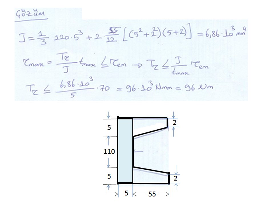
Örnek: Şekildeki profilin taşıyabileceği burulma momentini hesaplayınız.
G=80 Gpa τem=70 Mpa ϴem=0.22 rd/m 5 55 2 110

61
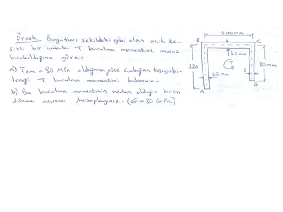
Örnek: Boyutları şekilde verilen ‘L’ profil kesitin imal edildiği malzemenin emniyet gerilmesi 60 MPa dır. Birim dönme açısı için konulan sınır 0.2 rad/m olduğuna göre kesitin taşıyabileceği burulma momentini hesaplayınız. G=80 GPa.

62
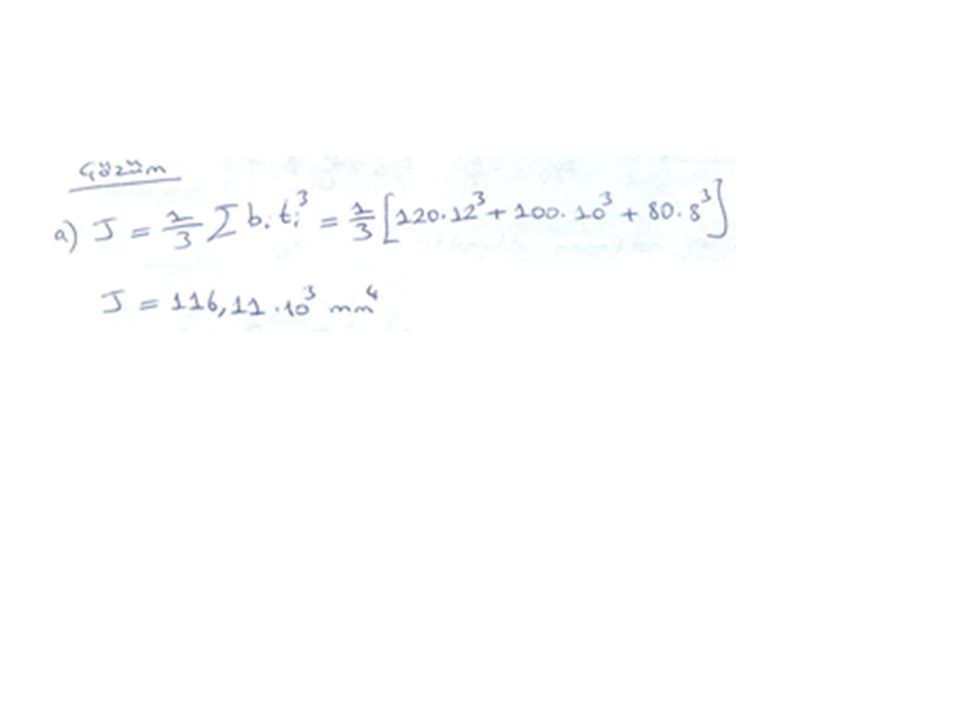
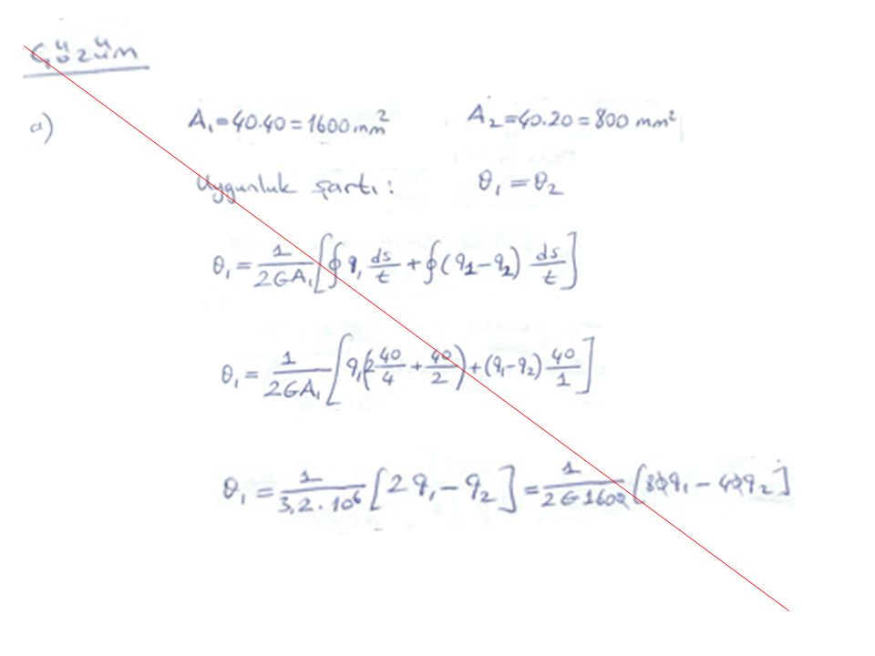
Çözüm: Kesitin polar atalet momenti:

63
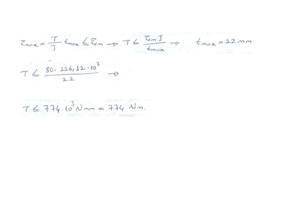
Emniyet gerilmesine göre burulma momentinin bulunması:

64
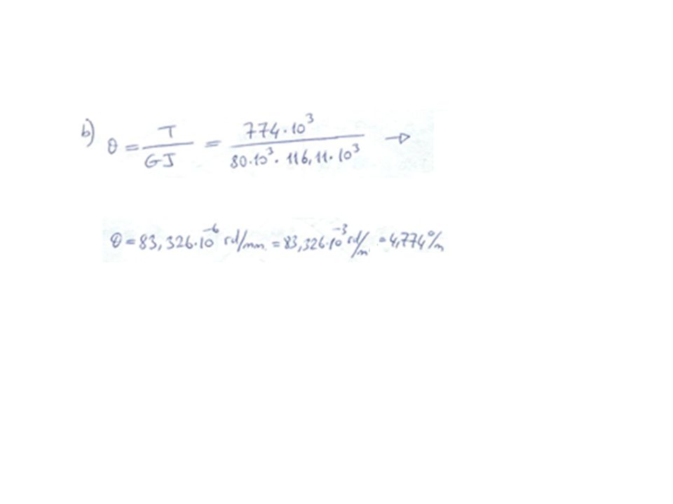
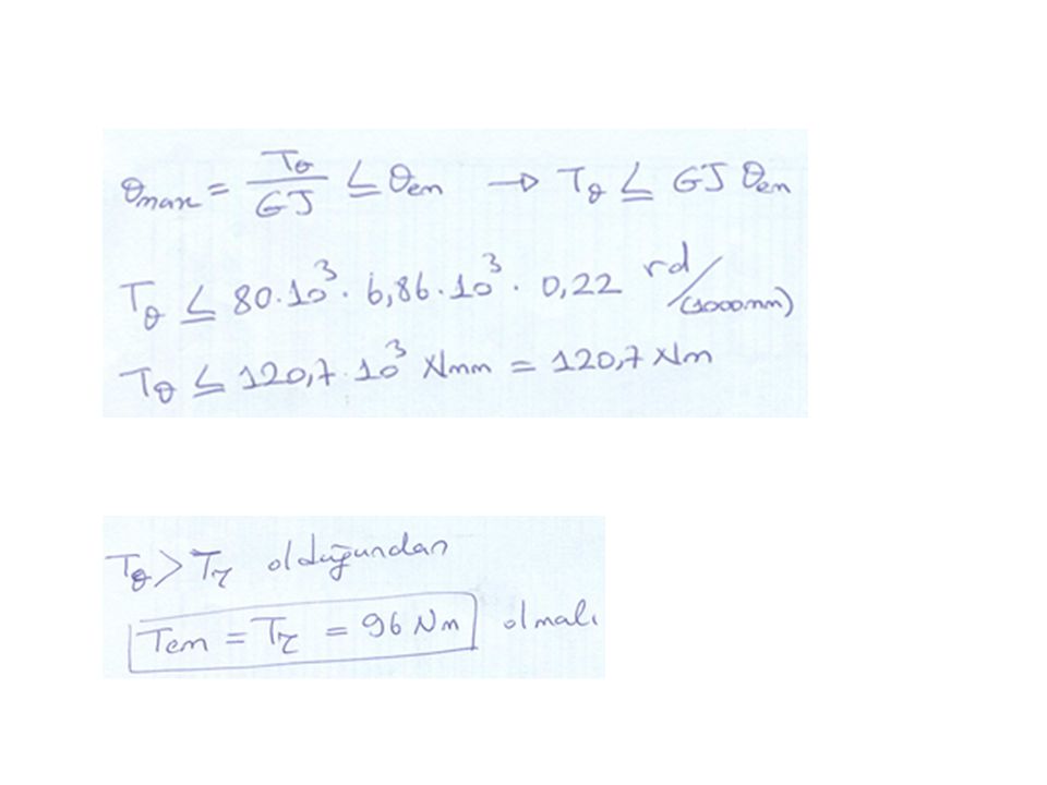
Emniyetli birim dönme açısına göre burulma momentinin bulunması:
Buna göre olduğundan alınır.

65
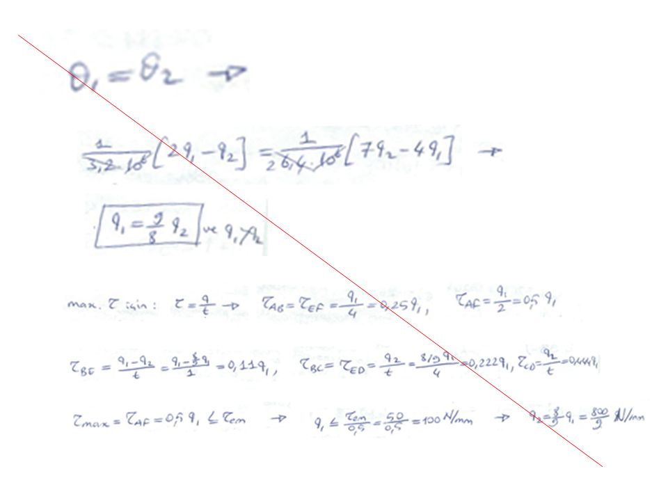
Kompozit profiller Örnek: Boyutları şekilde verilen ‘T’ profil kesitte 1 ve 2 parçaları, kayma modülleri sırası ile G1=60 GPa ve G2=80 GPa olan farklı malzemelerden imal edilmiştir. Buna göre bu profilin taşıyabileceği burulma momentini hesaplayınız. 100 mm 120 mm 8 7 1 2 Kayma emniyet gerilmeleri

66
Çözüm: Kesitlerin burulma rijitlikleri:

67
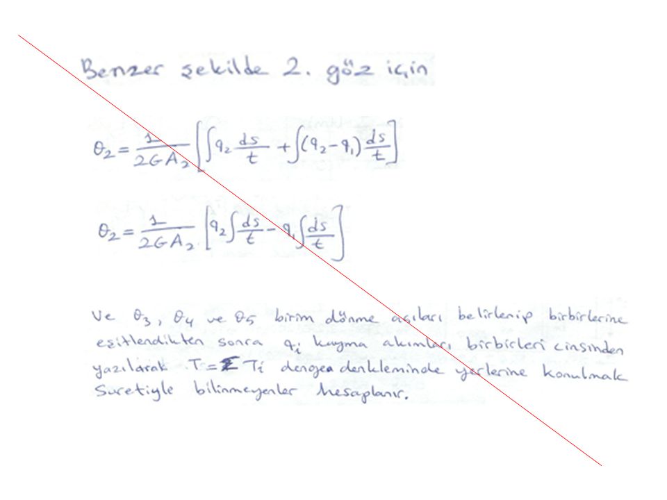
Kesitlerde oluşan iç burulma momentleri-dış burulma momenti dengesi:

68
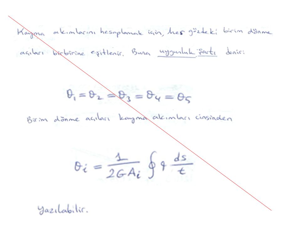
Kesitlerde oluşan burulma açıları birbirine eşittir (Uygunluk Şartı):
:")
69
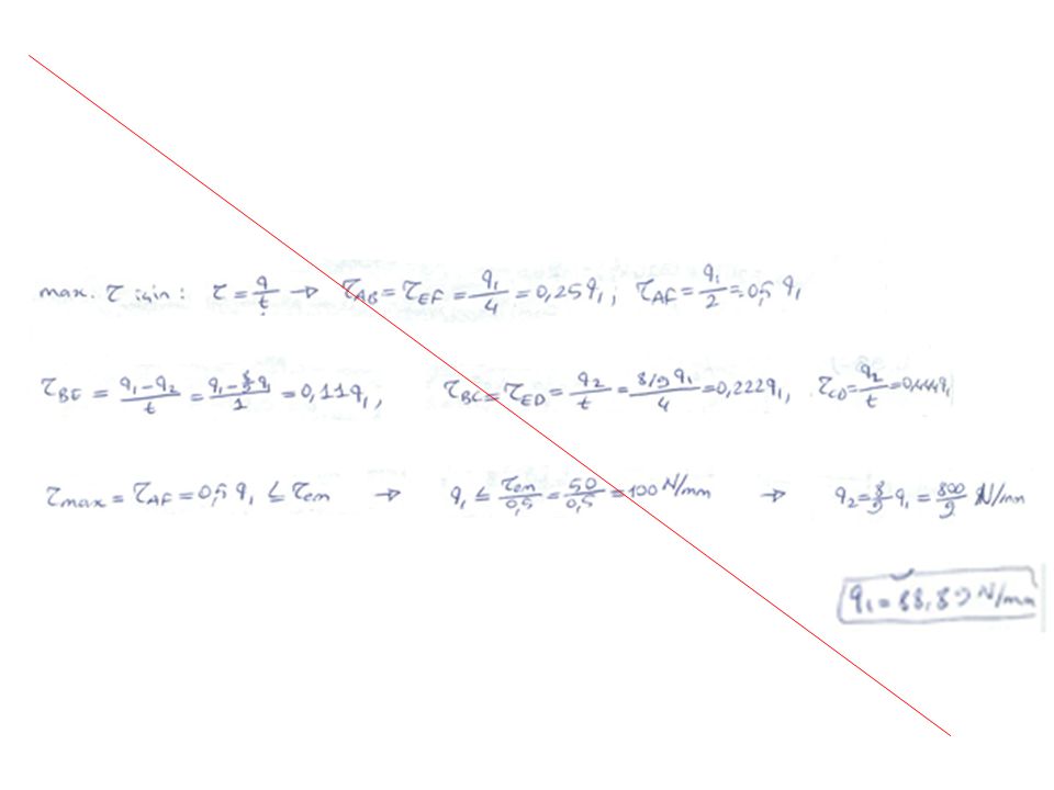
Kesitlerdeki kayma gerilmeleri:
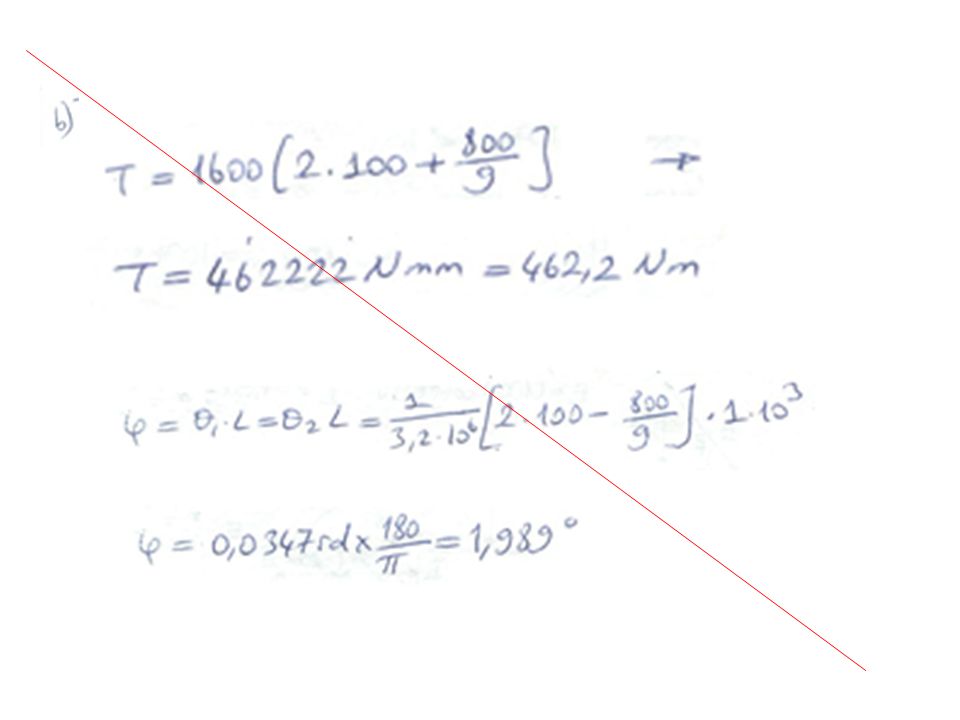
Birleşik kesitin taşıyabileceği emniyetli burulma momentleri: ve Son iki denklemden bulunacak en küçük burulma momenti emniyetli değer olarak alınır.

70
Birinci kesite göre, birleşik kesitin taşıyabileceği emniyetli burulma yükü aşağıdaki gibi bulunur:

71
Birinci kesite göre, birleşik kesitin taşıyabileceği emniyetli burulma yükü aşağıdaki gibi bulunur:
Buna göre, emniyetli burulma momenti küçük olan değerdir:

84
Example: For the channel section, and neglecting stress concentrations,
determine the maximum shearing stress caused by a 800-N vertical shear applied at centroid C of the section, which is located to the right of the center line of the web BD. t V h b A C B E D x b=100 mm h=150 mm t=3 mm

85
Solution: V A C B E D V A C B E D V A C B E D A C B E D T = = + T

86
V A C B E D

87
A C B E D O T

88
The maximum shearing stress

89
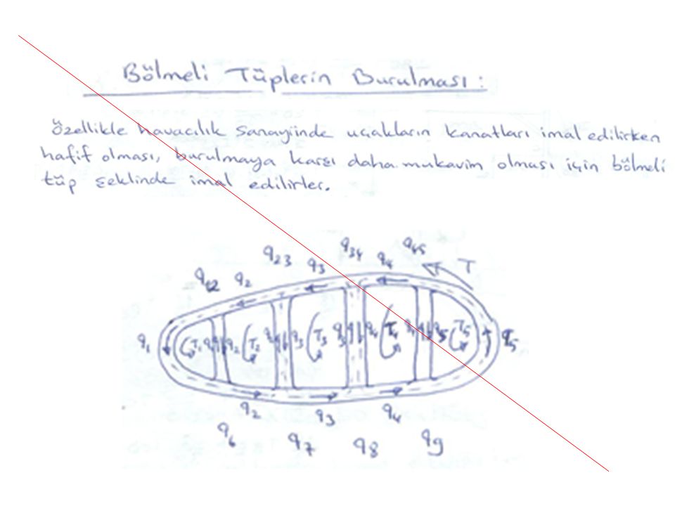
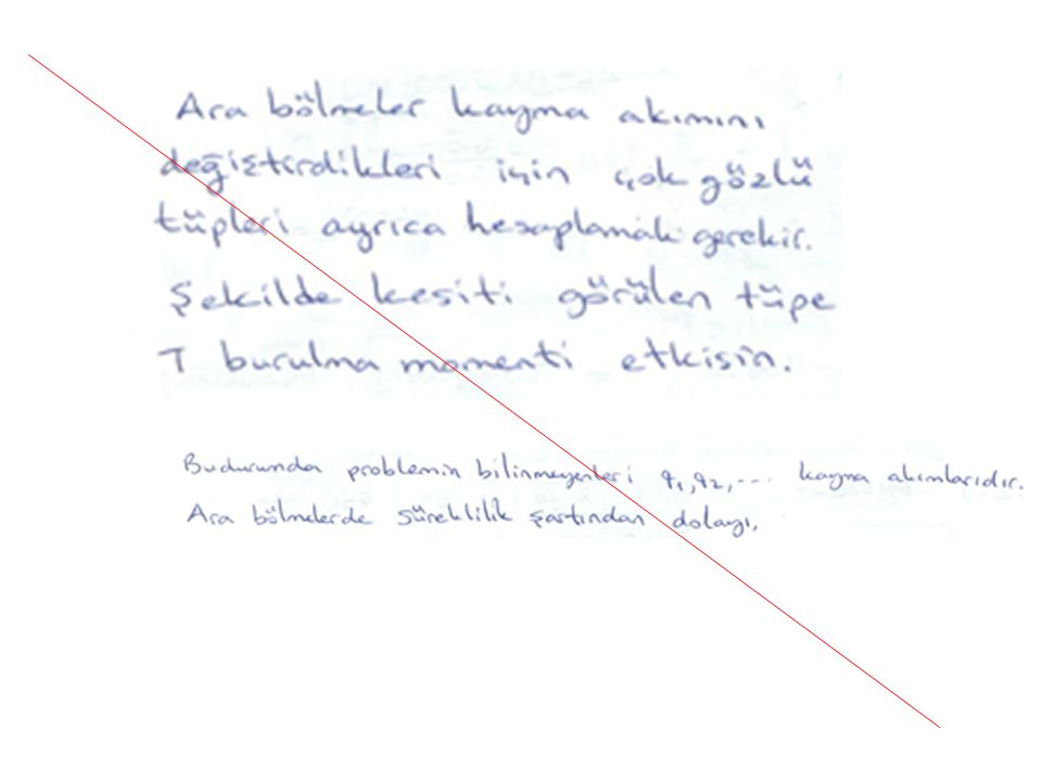
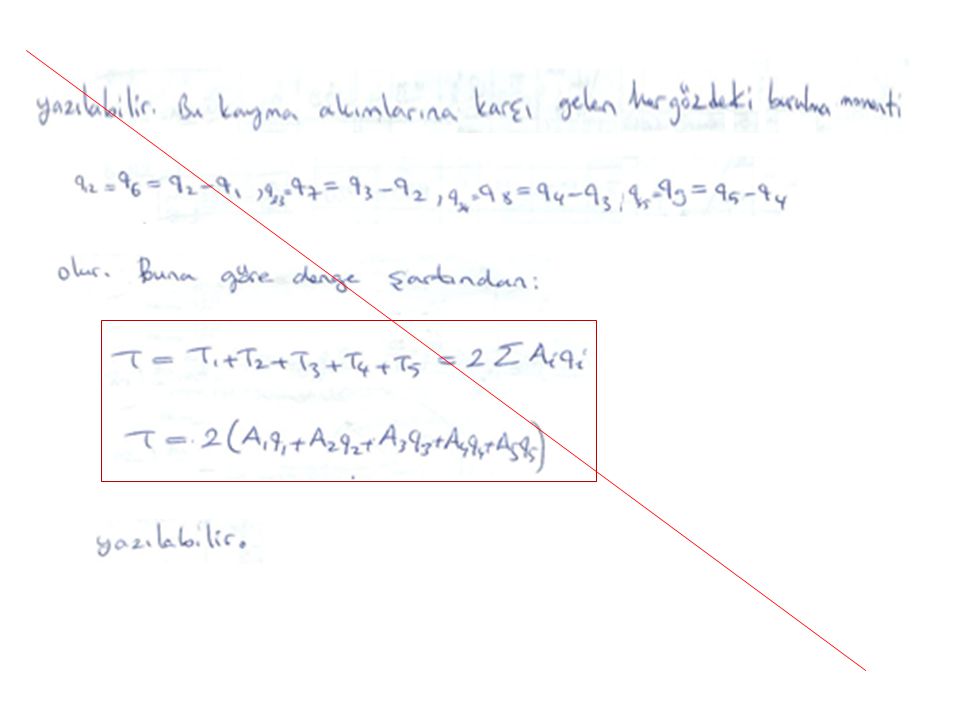
Bölmeli Tüplerin Burulması
(İleri Mukavemet)
")
Benzer bir sunumlar


 Sistemlerin Frekans Tepkileri>")


 MOMENTİ>")


 ve BURKULMA (Buckling) M.Feridun Dengizek>")