Sunuyu indir
Sunum yükleniyor. Lütfen bekleyiniz

1
Dolgu Barajlarda Sızma Analizi

2
Ç.Ü.İnş.Müh.Böl.

3
Recep YURTALÇ.Ü.İnş.Müh.Böl.

4
Recep YURTALÇ.Ü.İnş.Müh.Böl.

5
Recep YURTALÇ.Ü.İnş.Müh.Böl.

6
Recep YURTALÇ.Ü.İnş.Müh.Böl.

7
Recep YURTALÇ.Ü.İnş.Müh.Böl.

8
Recep YURTALÇ.Ü.İnş.Müh.Böl.

9
Recep YURTALÇ.Ü.İnş.Müh.Böl.

10
Teton Dam Failure 1 - View northwest toward right abutment probably between 10:30 and 11 AM. The leak is the dark brown streak on the dam face near the gray bedrock in the left half of the photo. The speck above the leak near the top of the dam is a D-9 bulldozer that is heading down to the leak to push dirt into it futily. Photo by Mrs. Eunice Olson, 5 June 1976.

11
Teton Dam Failure 2 - View northwest toward right abutment. The leak is the muddy brown streak on the dam face near the gray bedrock. Note position of leak relative to abutment bedrock for comparison in subsequent pictures. Photo by Mrs. Eunice Olson, 5 June 1976.

12
Teton Dam Failure 3 - View northwest toward right abutment. Muddy water issues out of the hole about two-thirds up the face of the dam and begins to pond at the toe. Photo by Mrs. Eunice Olson, 5 June 1976.

13
Teton Dam Failure 4 - View northwest toward right abutment. The hole in the dam face enlarges upward. Compare with photo #2. Photo by Mrs. Eunice Olson, 5 June 1976.

14
Teton Dam Failure 5 - View northwest toward right abutment. The hole in the dam face enlarges upward, erosion has cut into the bedrock of the abutment, another brown collapse hole forms above the main leak, and muddy brown water begins to flood works at the toe of the dam. Photo by Mrs. Eunice Olson, 5 June 1976.

15
Teton Dam Failure 6 - View northwest toward right abutment. The leak hole has enlarged greatly, and erosion of the bedrock abutment intensifies. Photo by Mrs. Eunice Olson, 5 June 1976.

16
Teton Dam Failure 7 - View northwest toward right abutment. The hole in the dam face continues to enlarge upward near the crest of the dam, the rush of water increases markedly, and erosion cuts deep into bedrock of the abutment. Photo by Mrs. Eunice Olson, 5 June 1976.

17
Teton Dam Failure 8 - View northwest toward right abutment. The hole in the dam face begins to cut across the crest of the dam, the rush of water increases even more, and the works at the toe are flooded. Photo by Mrs. Eunice Olson, 5 June 1976..

18
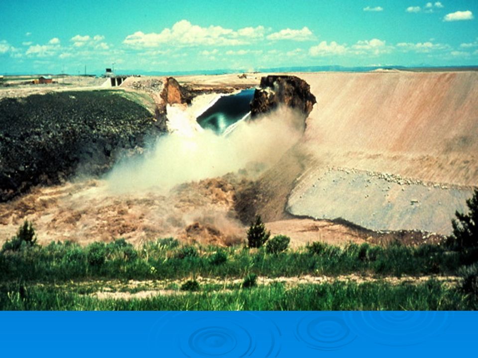
Teton Dam Failure 9 - View northwest toward right abutment. The dam is breached at 11:57 AM, the rush of muddy brown water is violent. Note how the breach widens in subsequent photos. Photo by Mrs. Eunice Olson, 5 June 1976

19
Teton Dam Failure 10 - View northwest toward right abutment. Water spills unchecked through the breach. Photo by Mrs. Eunice Olson, 5 June 1976.

20
Teton Dam Failure 11 - View northwest toward right abutment. The breach widens. Photo by Mrs. Eunice Olson, 5 June 1976.

21
Teton Dam Failure 12 - View northwest toward right abutment. The flow of water increases as the breach widens. Photo by Mrs. Eunice Olson, 5 June 1976.

22
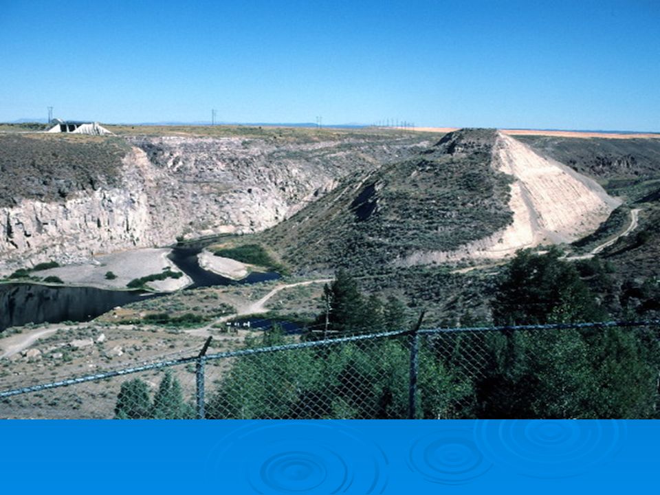
Teton Dam Failure 13 - View northwest toward the center of the breach from a position farther back than for photos 1-12. The flow is completely unchecked. All works at the toe of the dam are completely flooded. Photo by Mrs. Eunice Olson, 5 June 1976.

25
Recep YURTALÇ.Ü.İnş.Müh.Böl.

26
Sızma Analizi Freatik hattın belirlenmesi Freatik hattın belirlenmesi Sızma miktarının hesabı Sızma miktarının hesabı h A Freatik Hat

27
h A

28
Recep YURTALÇ.Ü.İnş.Müh.Böl.

29
Recep YURTALÇ.Ü.İnş.Müh.Böl.

30
Recep YURTALÇ.Ü.İnş.Müh.Böl.

31
DOLGU BARAJLARDA SIZMA ANALİZİ Freatik Hattın Hesabı Ve Çizimi 1) Barajdaki su yüksekliği belirlenir (h) 2) Baraj memba yüzü ile su yüzeyinin kesim noktası (Bo) olarak tanımlanır. 3) Memba şevinin tabandaki ilk noktasından yukarı doğru bir dik çıkılır, ve bu çizgi ile Bo arasındaki mesafe (S) olarak tanımlanır. 4) Su yüzünde Bo noktasından sola doğru =0.30×S kadar mesafede B noktası tanımlanır. 5) B noktası ile A noktası (mansap şevinin tabandaki ilk uç noktası) bir çizgi ile birleştirilir. Bu çizgi R olarak tanımlanır. B – A yatay mesafesi d ile, B-A düşey mesafesi h ile adlandırılınca formulü ile hesaplanır.
 Memba şevinin tabandaki ilk noktasından yukarı doğru bir dik çıkılır, ve bu çizgi ile Bo arasındaki mesafe (S) olarak tanımlanır. 4) Su yüzünde Bo noktasından sola doğru =0.30×S kadar mesafede B noktası tanımlanır. 5) B noktası ile A noktası (mansap şevinin tabandaki ilk uç noktası) bir çizgi ile birleştirilir. Bu çizgi R olarak tanımlanır. B – A yatay mesafesi d ile, B-A düşey mesafesi h ile adlandırılınca formulü ile hesaplanır..")
32
DOLGU BARAJLARDA SIZMA ANALİZİ 6) Mansap taban uç noktası (A) dan yukarı doğru y doğrusu çizilir ve bu çizgi üzerinde aşağıdaki formülle hesaplanan y o ın yeri işaretlenir. 7) Mansap taban uç noktası (A) dan sağa doğru yatay olarak x doğrusu çizilir ve bu çizgi üzerinde aşağıdaki formülle hesaplanan a o ın yeri işaretlenir. 8) Mansap taban uç noktası (A) dan mansap şevi üzerindeki C noktası aşağıdaki formülle hesaplanarak işaretlenir. Böylece C = l + l mesafesi bulunmuş olur.
 Mansap taban uç noktası (A) dan sağa doğru yatay olarak x doğrusu çizilir ve bu çizgi üzerinde aşağıdaki formülle hesaplanan a o ın yeri işaretlenir. 8) Mansap taban uç noktası (A) dan mansap şevi üzerindeki C noktası aşağıdaki formülle hesaplanarak işaretlenir. Böylece C = l + l mesafesi bulunmuş olur..")
33
DOLGU BARAJLARDA SIZMA ANALİZİ 8) Co noktasını bulmak için, mansaptaki açısına bağlı olarak tablodan e değeri okunur. 9) formülünde (e) ve ( l + l) belli olduğu için formulden ( l) hesaplanır ve buna göre Co ın yeri işaretlenir. 10) formulünde yo daha önce belirlenmişti. y için keyfi değerler vererek bunlara karşılık x değerleri formülden hesaplanır. Hesaplanan x ve y değerleri karşılıklı olarak şekil özerine işaretlenip birleştirilirse freatik hat elde edilmiş olur.
 formülünde (e) ve ( l + l) belli olduğu için formulden ( l) hesaplanır ve buna göre Co ın yeri işaretlenir. 10) formulünde yo daha önce belirlenmişti. y için keyfi değerler vererek bunlara karşılık x değerleri formülden hesaplanır. Hesaplanan x ve y değerleri karşılıklı olarak şekil özerine işaretlenip birleştirilirse freatik hat elde edilmiş olur..")
34
h S BoBo S x 0.30 d B

35
h S BoBo d x y A yoyo a o = y o / 2 B

36
h S BoBo S x 0.30 d x y A yoyo a o = y o / 2 Teorik Freatik Hat l + l C B

37
h S BoBo S x 0.30 d x y A yoyo a o = y o / 2 Teorik Freatik Hat l + l C l ll CoCo B

38
h S BoBo S x 0.30 d x y A yoyo a o = y o / 2 Teorik Freatik Hat l + l C l ll CoCo Pratik Freatik Hat B

39
h S BoBo S x 0.30 d x y A yoyo a o = y o / 2 Teorik Freatik Hat l + l C l ll CoCo Pratik Freatik Hat B

40
h A S BoBo S x 0.30 d x y

41
h A S BoBo d x y yoyo l + l

42
h A S BoBo S x 0.30 d x y yoyo l + l Teorik Freatik Hat C = C o Pratik Freatik Hat

43
h

44
h x y yoyo S BoBo S x 0.30 d

45
h x y yoyo S BoBo d l + l C Teorik Freatik Hat l l l CoCo

46
h x y yoyo S BoBo S x 0.30 d l + l C Teorik Freatik Hat l l l CoCo Pratik Freatik Hat

47
Gövdede Sızma Debisi 30° => q = birim boydaki sızma debisi (m³/s/m) k = permeabilite katsayısı I = hidrolik eğim (memba ve mansap su seviyeleri arasındaki farkın geçirimsiz çekirdek tabanına oranı A = temelden geçirimsiz tabakaya kadar olan mesafe
 k = permeabilite katsayısı I = hidrolik eğim (memba ve mansap su seviyeleri arasındaki farkın geçirimsiz çekirdek tabanına oranı A = temelden geçirimsiz tabakaya kadar olan mesafe")
48
Gövdede Sızma Debisi Akım Ağları Biliniyorsa: h n m

49
Temelde Sızma Debisi Toplam Sızma = Gövde + Temel Toplam Sızma 0.5 m³/gün/m h A Geçirimsiz Tabaka B

50
Örnek Şekilde verilen homojen toprak dolgu barajda k = 2 10 -5 mm/s olduğuna göre gövdedeki sızmayı bulunuz. h = 15 m

51
Örnek 1 2 3 4 5 2 4 6 1 3 5 7 8 9 10 11 m = 5 n = 11 k = 2 10 -5 mm/s h = 15 m

52
Örnek Şekilde verilen homojen toprak dolgu barajda k=1 10 -5 cm/s olduğuna göre freatik hattı ve sızma debisini belirleyiniz. 1 3 1 1.5 1 2.5 3 1 6 m Geçirimsiz Tabaka 12 m 10 m 2 m 20 m 30 m

53
Çözüm h = 20 m (max. Su yüksekliği) B = 132 m (baraj taban genişliği) S = h 3 = 20 3 = 60 mS = h 3 = 20 3 = 60 m B ‘nin yeri: S 0.30 = 60 0.30 = 18 mS 0.30 = 60 0.30 = 18 m
 B = 132 m (baraj taban genişliği) S = h 3 = 20 3 = 60 mS = h 3 = 20 3 = 60 m B ‘nin yeri: S 0.30 = 60 0.30 = 18 mS 0.30 = 60 0.30 = 18 m.")
54
Çözüm => = 33.69 => = 180 - 33.69 = 146.31

55
Çözüm A noktasından itibaren mansap şevi üzerindeki C noktasının tayini: A noktası ile C noktası arasındaki Co noktasının tayini (C den itibaren l kadar): = 146.31 için => e = 0.10 (Tablodan)
: = için => e = 0.10 (Tablodan)")
56
Pratik Freatik Hattın Belirlenmesi

57
1 3 1 1.5 1 2.5 3 1 6 m Geçirimsiz Tabaka 12 m 10 m 2 m h = 20 30 m 60 0.30= 18 m B Bo S = 20 3= 60 m d = 87-42 = 45 m 60-18 = 42 m 10 1.5 = 15 m 10 3 = 30 m 45 m 12 2.5 = 30 m 10 3 = 30 m 2 3 = 6 m 60 + 6 + 6 + 30 + 30 = 132 m 132 – 45 = 87 m y (+) x (-) Co C A Ao aoao yoyo R
 x (-) Co C A Ao aoao yoyo R")
58
Sızma Debisi: Gövdede : 30 < < 180 olduğundan Temelde: Toplam Sızma = q temel + q gövde = 0.039 + 0.036 = 0.075 0.50 m³/gün/m

Benzer bir sunumlar


 iki farklı veri grubu için de kullanılabilir. 1. Sınıflar2. Sınıflar A1015 B20 C3015.>")


