Sunuyu indir
Sunum yükleniyor. Lütfen bekleyiniz

1
-Normal kuvvet -Kesme kuvveti -Eğilme momenti -Burulma momenti
BİRLEŞİK YÜKLEMELER (Kesit tesirleri) STRESSES DUE TO COMBINED LOADING (Internal Forces) -Normal kuvvet -Kesme kuvveti -Eğilme momenti -Burulma momenti
 STRESSES DUE TO COMBINED LOADING (Internal Forces) -Normal kuvvet. -Kesme kuvveti. -Eğilme momenti. -Burulma momenti.")
2
Eğilmeli Burulma Bir mil eğilmeli burulma durumuna maruz kaldığında normal ve kayma gerilmeleri meydana gelir. Şekildeki kasnağa uygulanan P kuvveti A noktasına indirgendiğinde T=PR büyüklüğünde burulma momenti ankastre noktasına indirgendiğinde burulma ile birlikte M=PL büyüklüğünde eğilme ve V=P büyük-lüğünde kesme etkisi meydana gelir.

3
Özet olarak: Burulmadan dolayı kayma, Eğilmeden dolayı normal, Kesme kuvvetinden dolayı kayma gerilmesi meydana gelir.

4
3. Maddede belirtilen kesme kuvvetinin yol açtığı kayma gerilmesi milin merkezinde maksimum değerine ulaşmış olup, eğilme ve burulma gerilmelerine göre çok küçük olduğundan genellikle hesaba katılmaz. Eğilme gerilmeleri kesitin en üstünde ve en altında en büyük değerlerde meydana gelir.

5
Dolu miller için atalet momentleri ve gerilmeler:
- Polar atalet momenti ve kayma gerilmesi: - Kesit atalet momenti ve normal gerilme:

6
Buna göre asal gerilmeler:

7
Maksimum normal gerilmeye göre mil çapının bulunması:
Gevrek malzemeler normal gerilmelere hassas olduklarından maksimum normal gerilme emniyet gerilmesine eşitlenerek mil çapı bulunur: Dolu miller: ve

8
İçi boşaltılmış miller:
Atalet momentleri:

9
Kayma gerilmesi ve normal gerilme:
Asal gerilmeler:

10
Maksimum normal gerilmeye göre mil çapının bulunması:
ve

11
Maksimum kayma gerilmesine göre mil çapının bulunması
Sünek malzemeler kayma gerilmelerine hassas olduklarından maksimum kayma gerilmesi kayma emniyet gerilmesine eşitlenerek mil çapı bulunur: Dolu miller:

12
Maksimum kayma gerilmesine göre mil çapının bulunması

13
İçi boş miller: Kayma ve normal gerilmeleri: ve Asal gerilmeler:

14
Maksimum kayma gerilmesine göre mil çapının bulunması:

15
Örnek: Şekildeki mile bağlı kasnak teğetsel P kuvvetine maruz bırakıldığına göre mil çapını belirleyiniz. P=10 kN R=250 mm L=0.6 m P L 2R D

16
Çözüm: Eğilme ve burulma momentleri Max. normal gerilmeye göre mil çapının bulunması

17
Max. kayma gerilmesine göre mil çapının bulunması
olduğundan büyük olan değer kullanılır ve emniyetli çap olarak alınır.

18
Örnek: Çapı D=40 mm olan milin H ve K noktalarındaki normal ve kayma gerilmelerini hesaplayınız.
a=50 mm

19
Kesit tesirleri (İç kuvvetler):
Kesit özellikleri: y z x H K

20
H Noktasında oluşan gerilmeler:
Normal gerilme: y z x H K Kayma gerilmesi:

21
K Noktasında oluşan gerilmeler:
Normal gerilme: y z x H K Kayma gerilmesi:

22
Tüpün maruz kaldığı yükler
Örnek: Şekildeki tüp p iç basıncına, T burulma momentine ve N eksenel kuvvetine maruz kaldığına göre tüpte meydana gelen asal gerilmeleri ve maksimum kayma gerilmesini hesaplayınız. T=6 kNm p=2 Mpa N=20 kN d=122 mm D=128 mm T N d D p Tüpün kesit görünüşü Tüpün maruz kaldığı yükler

23
Çözüm: Tüpte oluşan gerilme bileşenleri y x

24
Tüpün polar atalet momenti ve oluşan kayma gerilmesi
Tüpte oluşan normal gerilme

25
Tüpün ortalama çapı ve cidar kalınlığı
Tüpte oluşan eksenel gerilme Tüpte oluşan teğetsel gerilme Eksenel bileşke gerilme

26
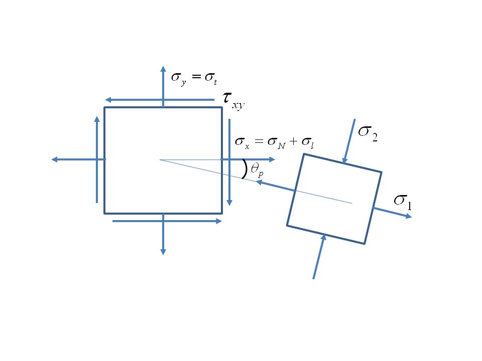
Gerilme elemanı üzerindeki gerilme bileşenleri
y x

27
Asal gerilmeler ve düzlemleri

29
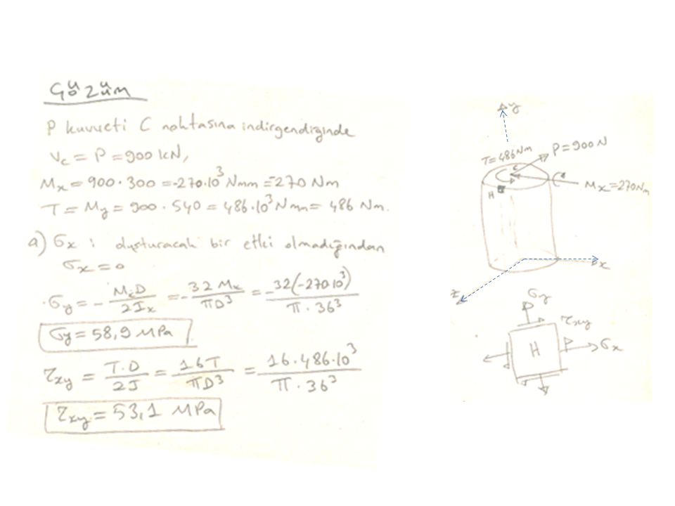
H noktasındaki normal ve kayma gerilmelerini hesaplayınız.
H noktasındaki asal gerilmeleri hesaplayıp doğrultularını bir eleman üzerinde gösteriniz. Örnek: Şekildeki ABD kolu A ucundan ankastre olup D ucuna P=900 N büyüklüğünde bir kuvvet uygulandığına göre:

31
Sample Problem 8.3 Solid shaft rotates at 480 rpm and transmits 30 kW from the motor to gears G and H; 20 kW is taken off at gear G and 10 kW at gear H. Knowing that τall = 50 MPa, determine the smallest permissible diameter for the shaft.

32
SOLUTION: Determine the gear torques and corresponding tangential forces. Find reactions at A and B. Identify critical shaft section from torque and bending moment diagrams. Calculate minimum allowable shaft diameter.

33
Relationship among Power, Speed and Torque in shafts
To determine the torque exerted on the shaft, we recall from elementary dynamics that the power P associated with the rotation of a rigid body subjected to a torque T is

34
Determine the gear torques and corresponding tangential forces.
Observing that f = 480 rpm = 8 Hz, we determine the torque and tangential forces exerted on gear E:

35
we determine the torques and tangential forces exerted on gears C and D:

36
We find reactions at A and B.

37
Bending-Moment and Torque Diagrams

38
MC or MD Critical Transverse Section:
We compute resultant bending moments at all potentially critical sections MC or MD

39
Critical Transverse Section:
we find equivalent moments for C and D : Cross-section at D Therefore, maximum value of equivalent moment occurs just to the right of D

40
Calculate minimum allowable shaft diameter accordig to maximum shearing stress:

41
Sample Problem 8.5 Three forces are applied to a short steel post as shown. Determine the principle stresses, principal planes and maximum shearing stress at point H.

42
SOLUTION STEPS: Determine internal forces in Section EFG. Evaluate normal stress at H. Evaluate shearing stress at H. Calculate principal stresses and maximum shearing stress. Determine principal planes.

43
Solution: Determine internal forces in Section EFG.
Section properties,

44
Evaluation of normal stress at H.

45
Evaluation of shearing stress at H.

46
H

47
Sample Problem 8.5 Calculate principal stresses and maximum shearing stress. Determine principal planes.

48
Eccentric Axial Loading in a Plane of Symmetry
Stress due to eccentric loading found by superposing the uniform stress due to a centric load and linear stress distribution due a pure bending moment Eccentric loading Validity requires stresses below proportional limit, deformations have negligible effect on geometry, and stresses not evaluated near points of load application.

49
Example 4.07 An open-link chain is obtained by bending low-carbon steel rods of 12-mm diameter into the shape shown. For a load of 700 N, determine a) maximum tensile and compressive stresses in the straight portion of the link, b) The distance between section the centroidal and neutral axis of a cross-section.
 maximum tensile and compressive stresses in the straight portion of the link, b) The distance between section the centroidal and neutral axis of a cross-section.")
50
SOLUTION STEPS: Find the equivalent centric load and bending moment Superpose the uniform stress due to the centric load and the linear stress due to the bending moment. Evaluate the maximum tensile and compressive stresses at the inner and outer edges, respectively, of the superposed stress distribution. Find the neutral axis by determining the location where the normal stress is zero.

51
SOLUTION Equivalent centric load and bending moment

52
SOLUTION Normal stress due to a centric load
Normal stress due to bending moment

53
Combined normal stresses
Maximum tensile and compressive stresses Neutral axis location

54
Sample Problem 4.8 The largest allowable stresses for the cast iron link are 30 MPa in tension and 120 MPa in compression. Knowing that determine the largest force P which can be applied to the link.

55
SOLUTION STEPS: Determine an equivalent centric load and bending moment. Superpose the stress due to a centric load and the stress due to bending. Evaluate the critical loads for the allowable tensile and compressive stresses. The largest allowable load is the smallest of the two critical loads.

56
Solution Determine centric and bending loads. M N d

57
Superpose stresses due to centric and bending loads

58
Evaluate critical loads for allowable stresses.
The largest allowable load

59
YAYLAR F

60
i) Helezonik bir yaydaki iç kuvvetler ve gerilmeler:
Şekil (a) da görülen helezonik yayı karakterize eden parametreler şunlardır: R: Yay yarıçapı d: Yay telinin çapı h: Helezon adımı (hatve) α: Helezon eğim açısı Helezon eğim açısı: P eksenel yüküne maruz helezonik yayda, Şekil (b) de görüldüğü gibi kesme kuvveti ve burulma momenti meydana gelir:
 da görülen helezonik yayı karakterize eden parametreler şunlardır: R: Yay yarıçapı. d: Yay telinin çapı. h: Helezon adımı (hatve) α: Helezon eğim açısı. Helezon eğim açısı: P eksenel yüküne maruz helezonik yayda, Şekil (b) de görüldüğü gibi kesme kuvveti ve burulma momenti meydana gelir:")
61
Kesit tesirlerinin (kesme kuvveti ve burulma momenti) neden olduğu toplam kayma gerilmesi süperpozisyon metodu ile bulunur, (Şekil a-b-c). Buna göre toplam kayma gerilmesi aşağıdaki gibi olur: Bu formülde , genellikle 1’ in yanında çok küçük kaldığından ihmal edilebilir.

62
Gerilme hesaplanırken k düzeltme faktörü kullanılabilir:

63
ii) Yayların uzaması Şekil (f) den görüldüğü gibi, ds uzunluğundaki yayın uzaması dδ dır. K1 ve K2 kesitleri arasında kalan ds uzunluğundaki yay parçasının rölatif dönme açısı aşağıdaki gibi olur: Birim dönme açısı ve ds uzunluğundaki yay telinin dönme açısı
 den görüldüğü gibi, ds uzunluğundaki yayın uzaması dδ dır. K1 ve K2 kesitleri arasında kalan ds uzunluğundaki yay parçasının rölatif dönme açısı aşağıdaki gibi olur: Birim dönme açısı ve. ds uzunluğundaki yay telinin dönme açısı.")
64
ds yay elemanında O noktası O’ noktasına yer değiştirdiğinde OO’=ds olur. Bu durumda yayın uzaması aşağıdaki gibi olur: Burada G kayma modülü, yay telinin polar atalet momenti ve s yay telinin uzunluğu olup aşağıdaki gibi bulunur: Burada n helezon (halka) sayısıdır.
 sayısıdır.")
65
Buna göre yayın uzaması aşağıdaki gibi olur:
veya

66
Örnek: 1.5 kN’luk bir yüke maruz helezonik yayın yarıçapı 100 mm, tel çapı 20 mm, halka sayısı 20 ve kayma modülü 84 GPa olduğuna göre; Maksimum gerilmeyi yaklaşık olarak, kesme kuvvetinin etkisini alarak ve düzeltme faktörünü kullanarak hesaplayınız. Yaydaki uzamayı hesaplayınız.

67
Çözüm: Yaklaşık olarak maksimum kayma gerilmesi:
Kesme kuvvetinin etkisini dikkate alarak maksimum kayma gerilmesi:

68
k düzeltme faktörü kullanılırsa sonuç aşağıdaki gibi olur:

69
Yayın uzaması aşağıdaki gibi bulunur:

70
Örnek: Titreşim sönümleyici olarak kullanılan yay sistemi P=240 N’luk düşey bir yüke maruz kaldığına göre; A ve B noktalarındaki tepkileri belirleyiniz. Yükün uygulandığı noktanın yer değiştirmesini hesaplayınız. R=100 mm d=10 mm G=90 GPa

71
Çözüm: a) Sistemin bütünü için denge denklemi [Şekil (a)]:
![Çözüm: a) Sistemin bütünü için denge denklemi [Şekil (a)]:](http://slideplayer.biz.tr/slide/2590978/9/images/71/%C3%87%C3%B6z%C3%BCm%3A+a%29+Sistemin+b%C3%BCt%C3%BCn%C3%BC+i%C3%A7in+denge+denklemi+%5B%C5%9Eekil+%28a%29%5D%3A.jpg "Çözüm: a) Sistemin bütünü için denge denklemi [Şekil (a)]:")
72
Sistemdeki iç kuvvetler, Şekil (b ve c)’den aşağıdaki gibi bulunur: :
Şekil (b) den Şekil (c) den
 den. Şekil (c) den.")
73
Sistemin uygunluk denklemi:

74
b) Yükün uygulandığı noktanın (C-C) yer değiştirmesi:
 Yükün uygulandığı noktanın (C-C) yer değiştirmesi:")
75
Örnek: Aynı malzemeden yapılmış ve helezon uzunlukları aynı olan iki yay iç içe geçirilerek P=380 N’luk bir yüke maruz bırakıldığına göre; Yaylardaki kuvvetleri hesaplayınız. A noktasının yer değiştirmesini hesaplayınız. n1=20 n2=10 G=90 Gpa d1=10 mm d2=14 mm R1=100 mm R2=140 mm

76
Çözüm: a) Sistemin uygunluk denklemi:
(1) ve (2) denklemi çözüldüğünde yay kuvvetleri aşağıdaki gibi bulunur:
 ve (2) denklemi çözüldüğünde yay kuvvetleri aşağıdaki gibi bulunur:")
77
b) δ1 veya δ2 den biri kullanılabilir:
 δ1 veya δ2 den biri kullanılabilir:")
78
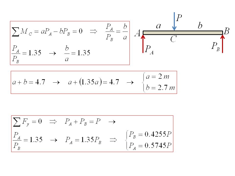
Örnek: Şekildeki L=4.7 m uzunluğundaki AB rijit çubuğu A ve B yayları ile desteklenerek P yüküne maruz bırakıldığına göre: Çubuğun yatay kalabilmesi için P kuvvetinin uygulanması gereken noktayı bulunuz. Emniyetle taşınabilecek P yükünü hesaplayınız. Çubuğun çökmesini belirleyiniz. Mekanik ozellikleri A yayı B yayı

79
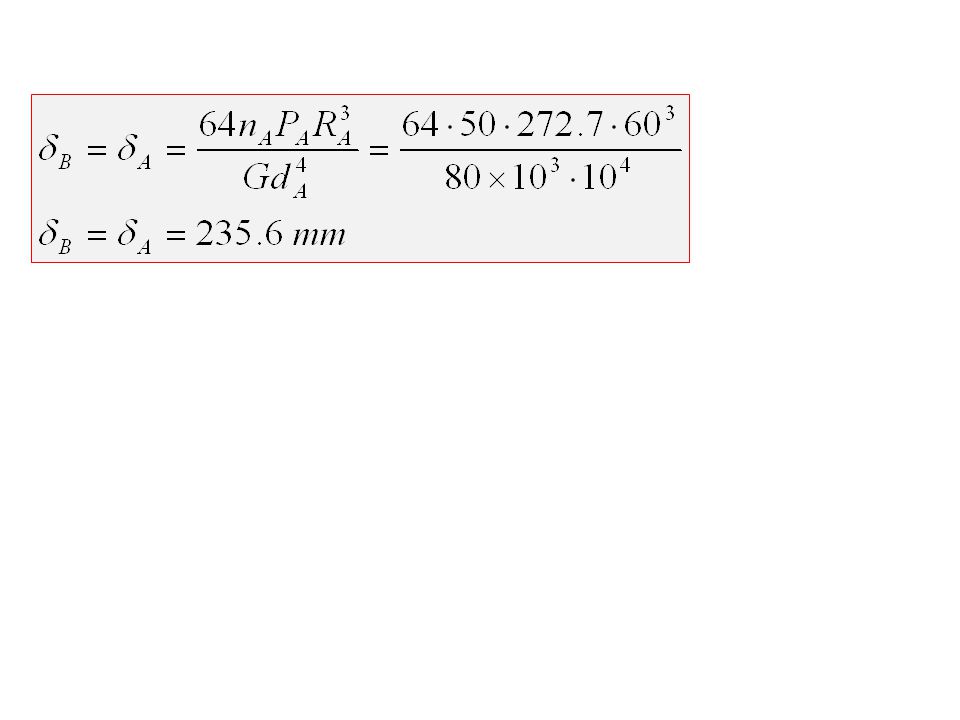
Çözüm

81
A yayına göre P kuvvetinin bulunması
A yayında oluşan maksimum kayma gerilmesi

82
B yayına göre P kuvvetinin bulunması
B yayında oluşan maksimum kayma gerilmesi

83
Emniyetle taşınabilecek yük küçük olan değer olmalıdır. Buna göre

86
1 2 3 Rijit kiriş A B C

88
Fig. Portions of an oilwell drill string.
EXAMPLE (Craig) During the drilling of an oil well, the section of the drill pipe at A (above ground level) is under combined loading due to a tensile force P = 70 kips and a torque T = 6 kip. ft, as illustrated in Fig. 1.The drill pipe has an outside diameter of 4.0 in. and an inside diameter of 3.64 in. Determine the maximum shear stress at point A on the outer surface of the drill pipe. The radial stress at this point is zero. The yield strength in tension of this drill pipe is 95 ksi. Fig. Portions of an oilwell drill string.
 During the drilling of an oil well, the section of the drill pipe at A (above ground level) is under combined loading due to a tensile force P = 70 kips and a torque T = 6 kip. ft, as illustrated in Fig. 1.The drill pipe has an outside diameter of 4.0 in. and an inside diameter of 3.64 in. Determine the maximum shear stress at point A on the outer surface of the drill pipe. The radial stress at this point is zero. The yield strength in tension of this drill pipe is 95 ksi. Fig. Portions of an oilwell drill string.")
89
Individual Stresses: we get the normal stress
Solution Stress Resultants: The stress resultants are given in the problem statement: F = P = 70 kips, T = 6 kip . ft (1) Individual Stresses: we get the normal stress
 Individual Stresses: we get the normal stress.")
92
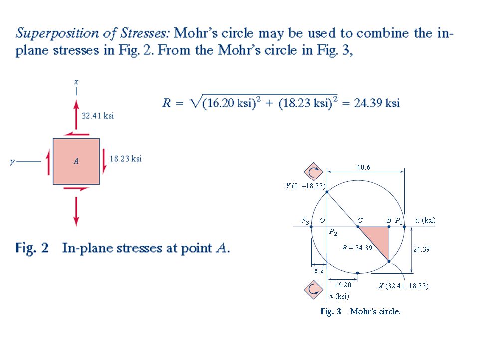
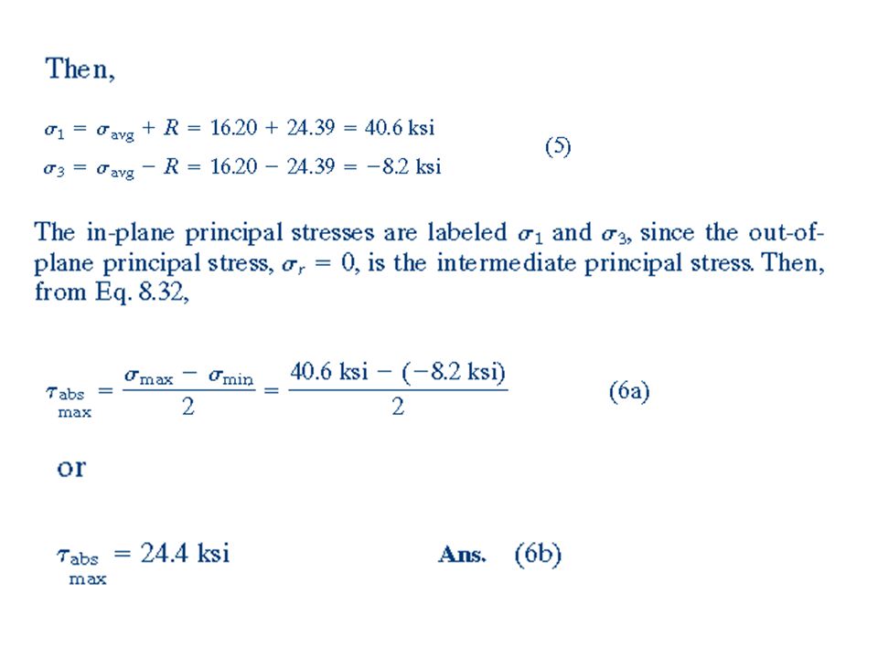
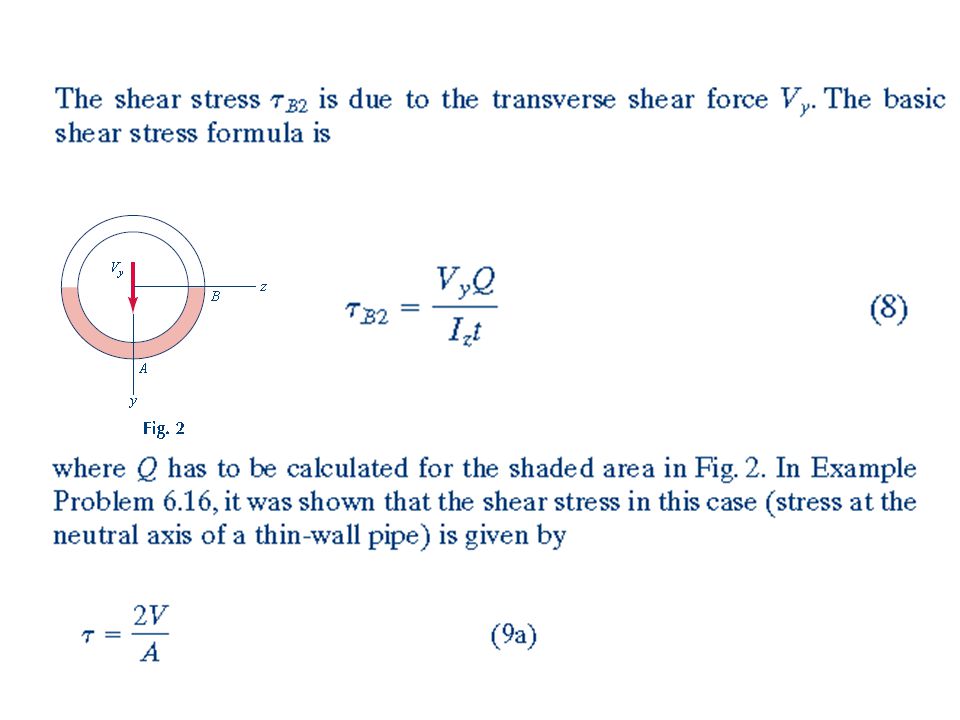
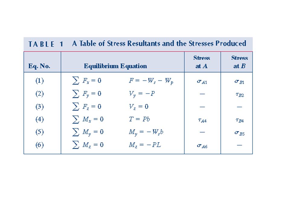
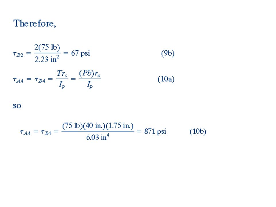
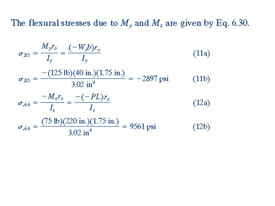
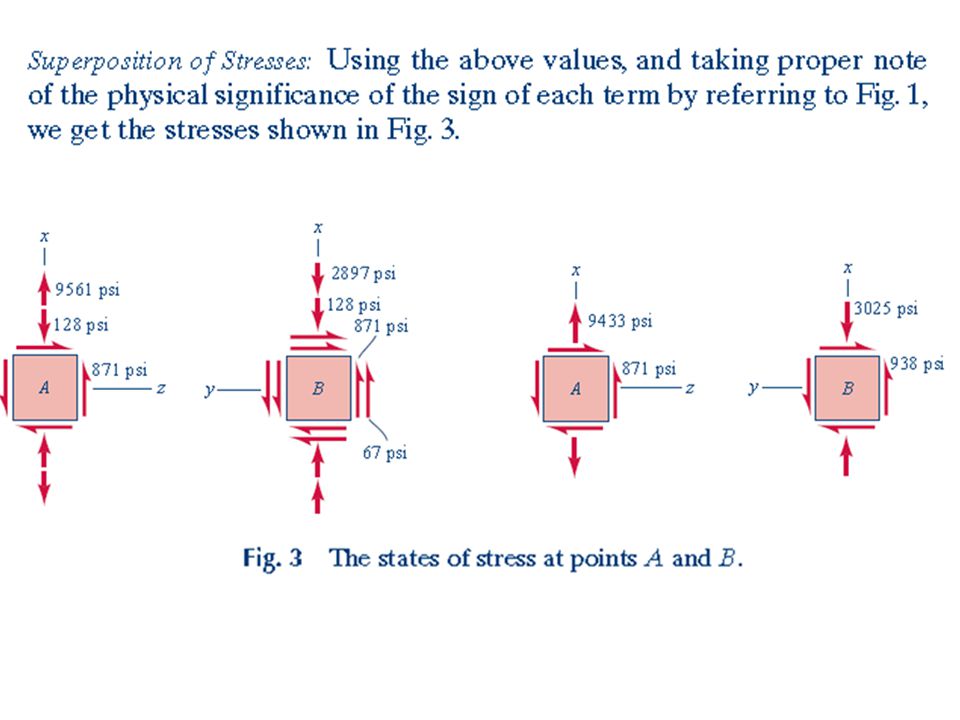
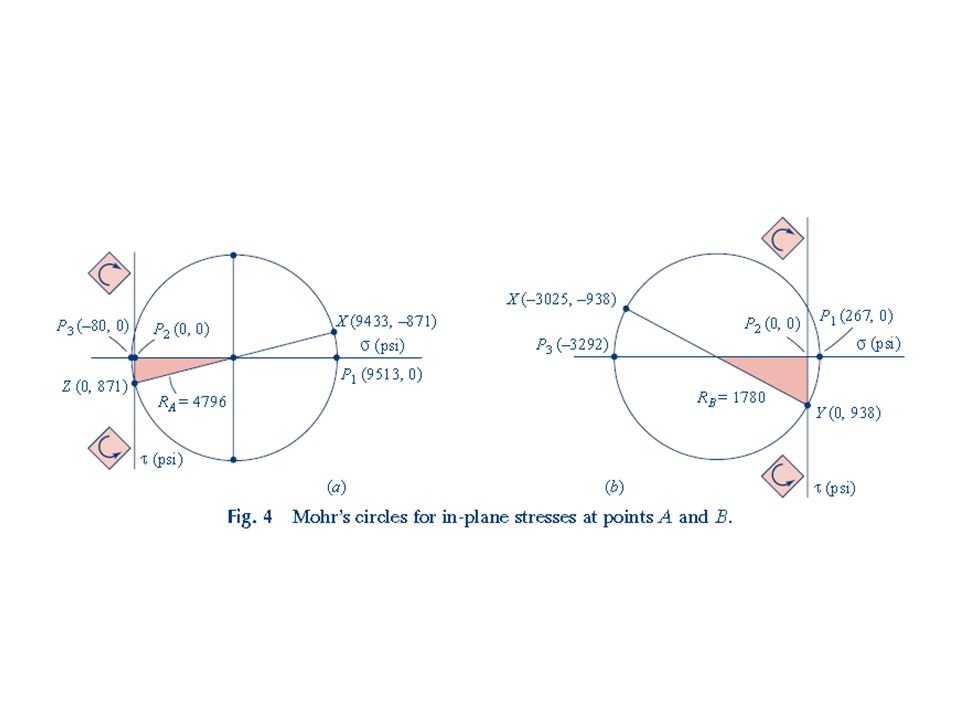
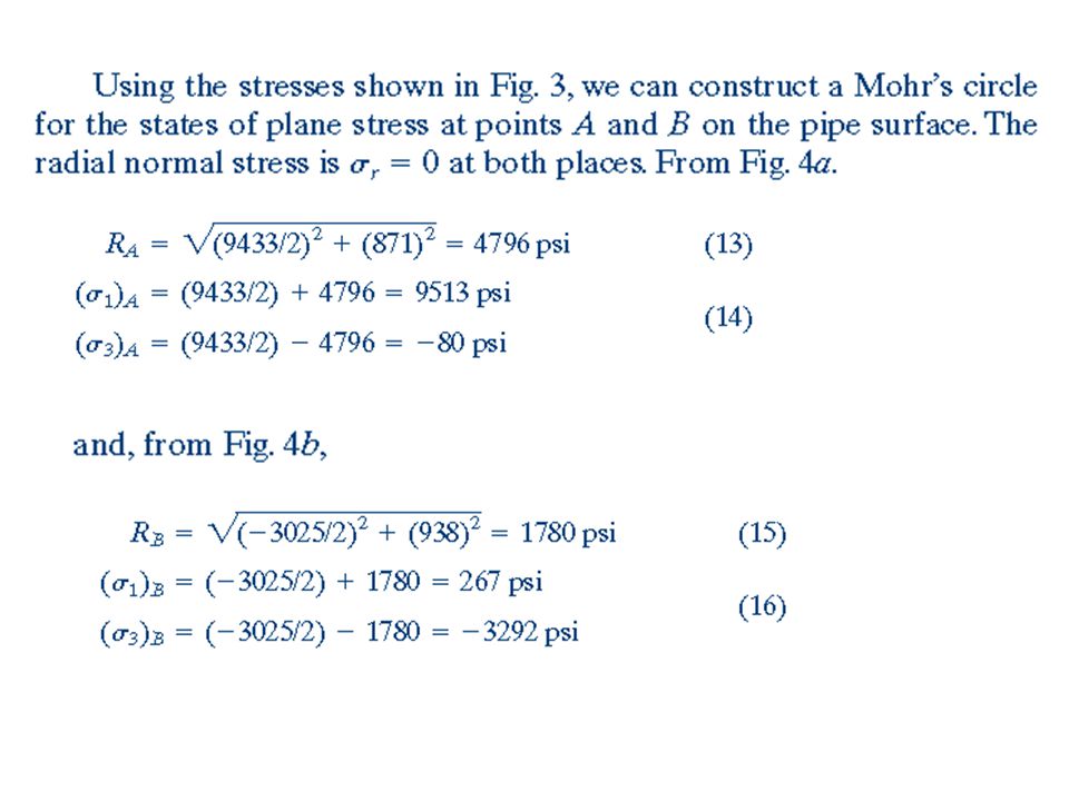
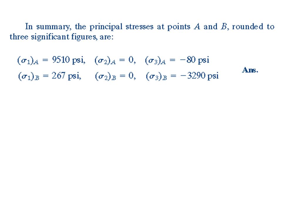
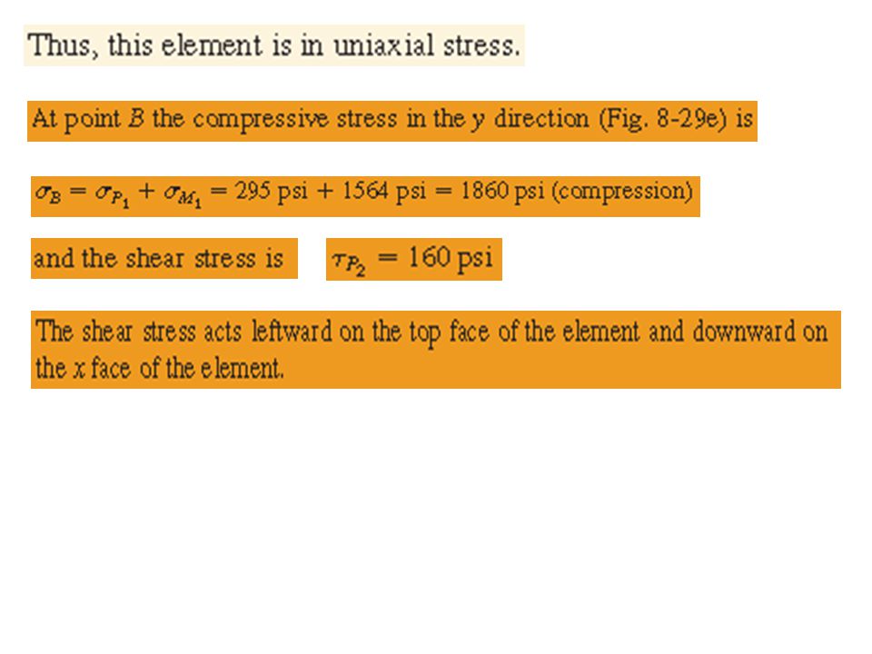
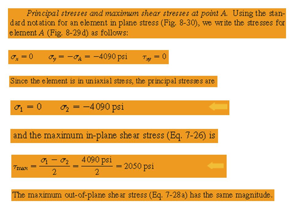
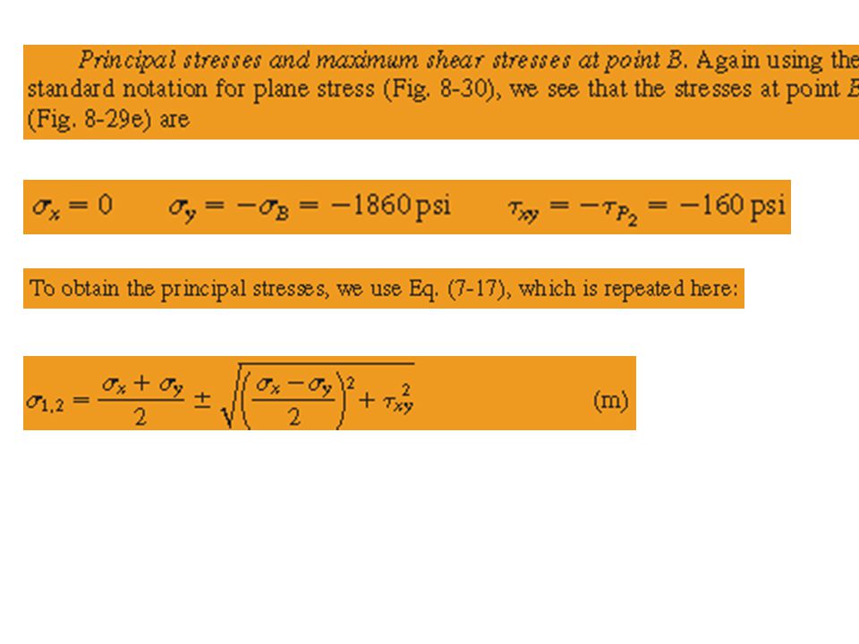
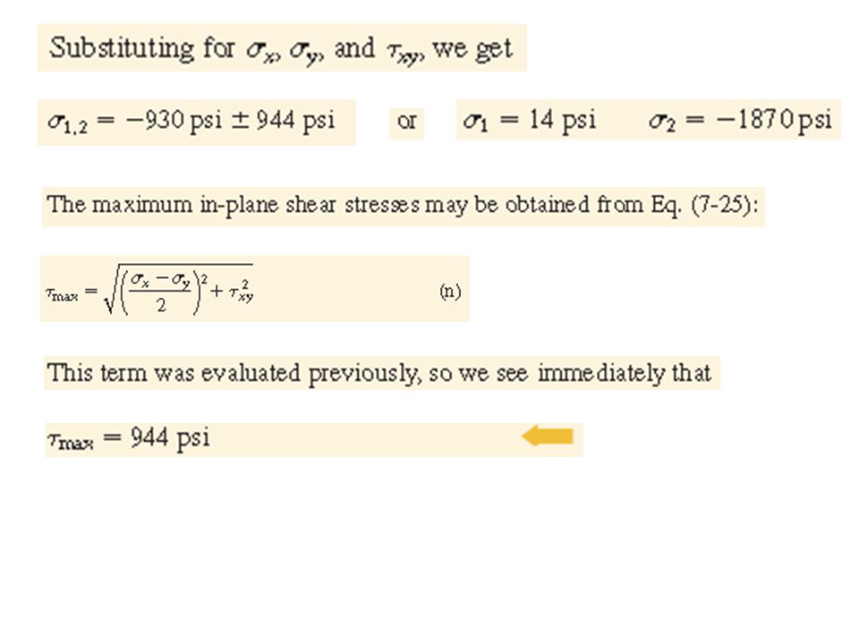
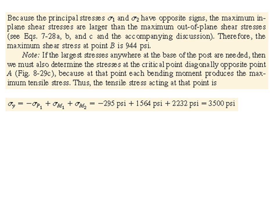
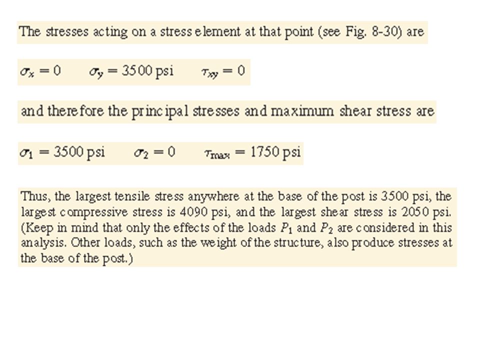
EXAMPLE Wind blowing on a sign produces a pressure whose resultant, P, acts in the y direction at point C, as shown in Fig. 1.The weight of the sign, Ws, acts vertically through point C, and the thin-wall pipe that supports the sign has a weight WP. Following the procedure outlined at the beginning of Section 9.4, determine the principal stresses at points A and B, where the pipe column is attached to its base. Use the following numerical data.

102
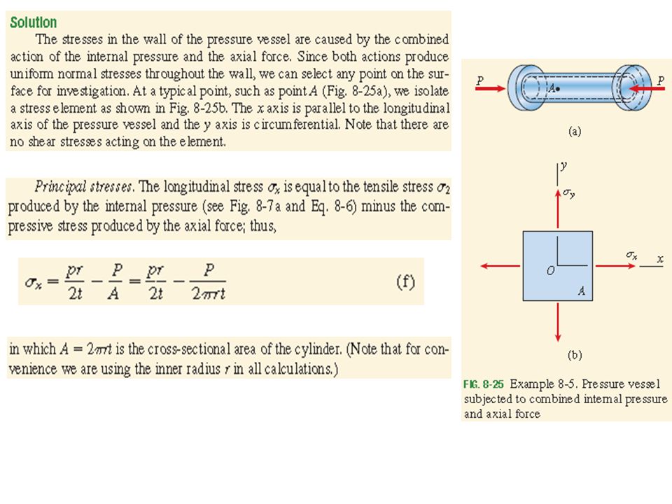
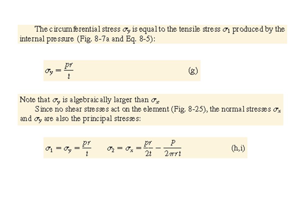
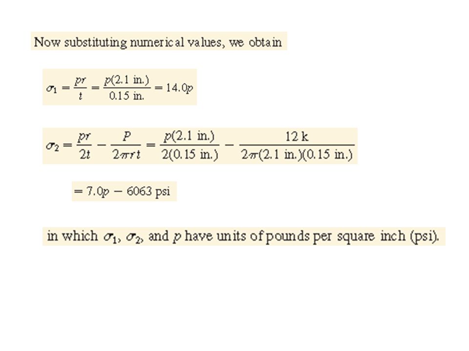
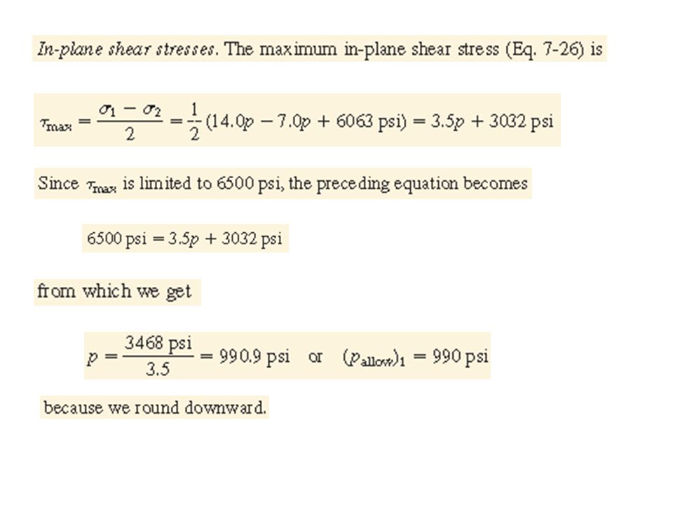
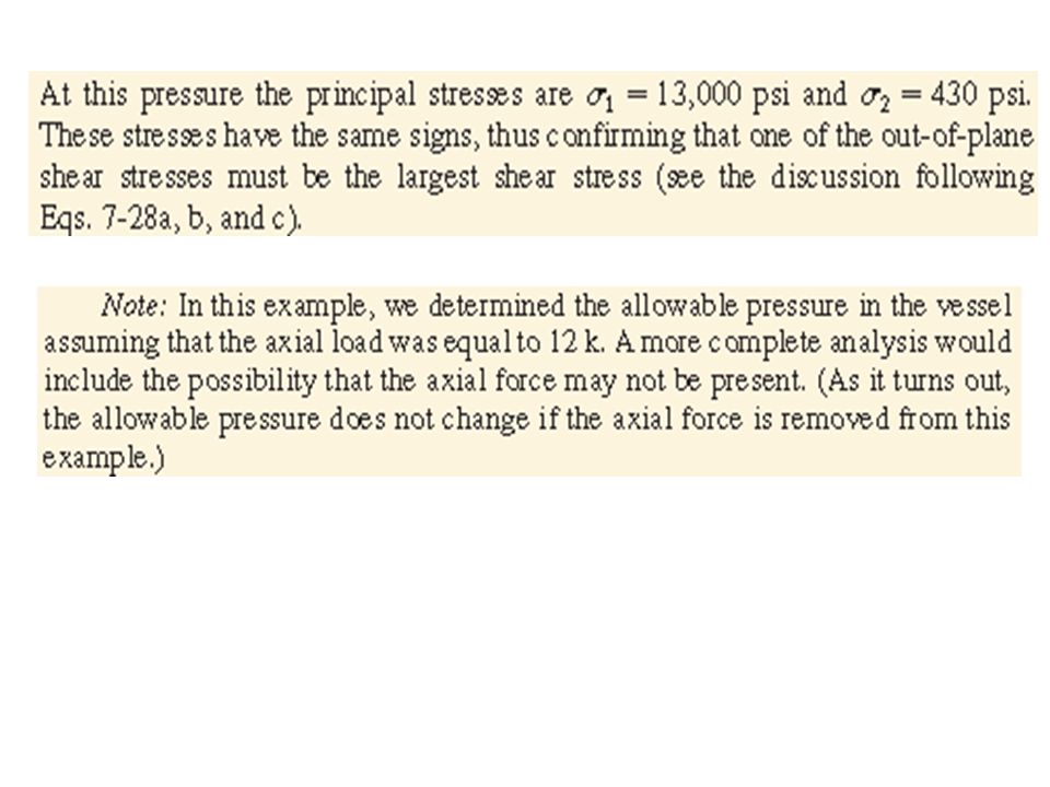
Example: A thin-walled cylindrical pressure vessel with a circular cross section is subjected to internal gas pressure p and simultaneously compressed by an axial load P=12 k (Fig. 8-25a). The cylinder has inner radius r=2.1 in. and wall thickness t=0.15 in. Determine the maximum allowable internal pressure pallow based upon an allowable shear stress of 6500 psi in the wall of the vessel.

109
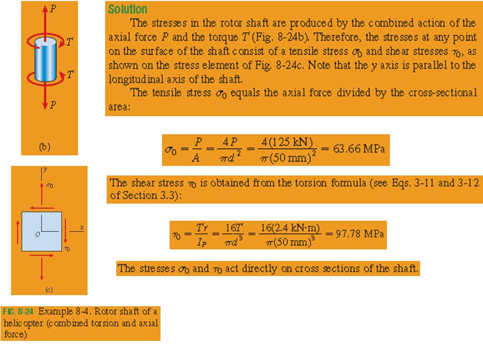
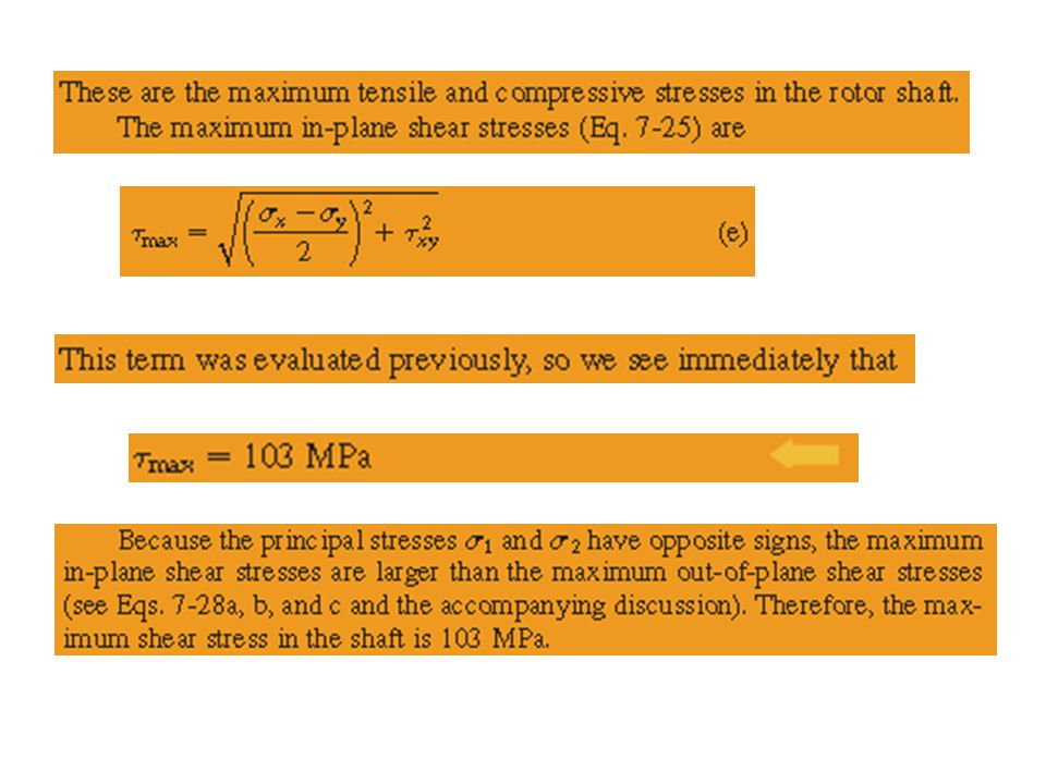
Example (GERE): The rotor shaft of a helicopter drives the rotor blades that provide the lifting force to support the helicopter in the air. As a consequence, the shaft is subjected to a combination of torsion and axial loading. For a 50-mm diameter shaft transmitting a torque T=2.4 kNm and a tensile force P=125 kN, determine the maximum tensile stress, maximum compressive stress, and maximum shear stress in the shaft.

113
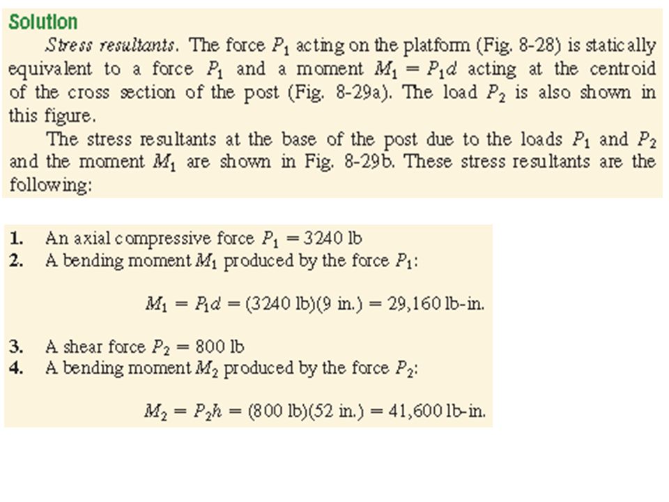
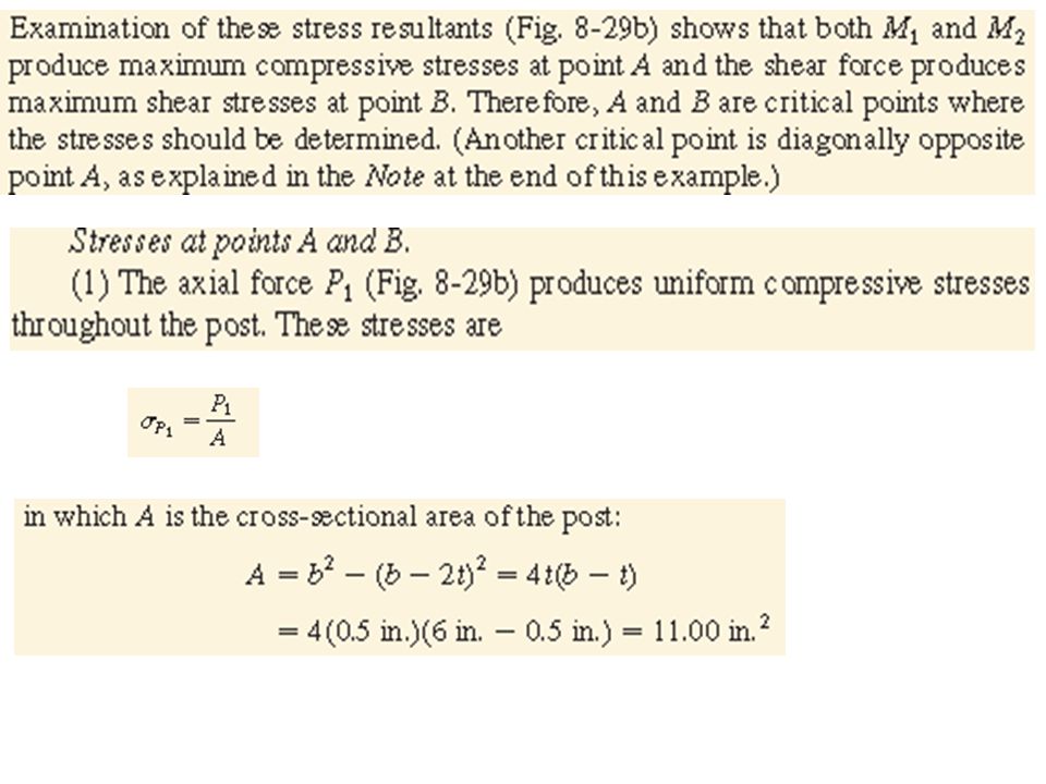
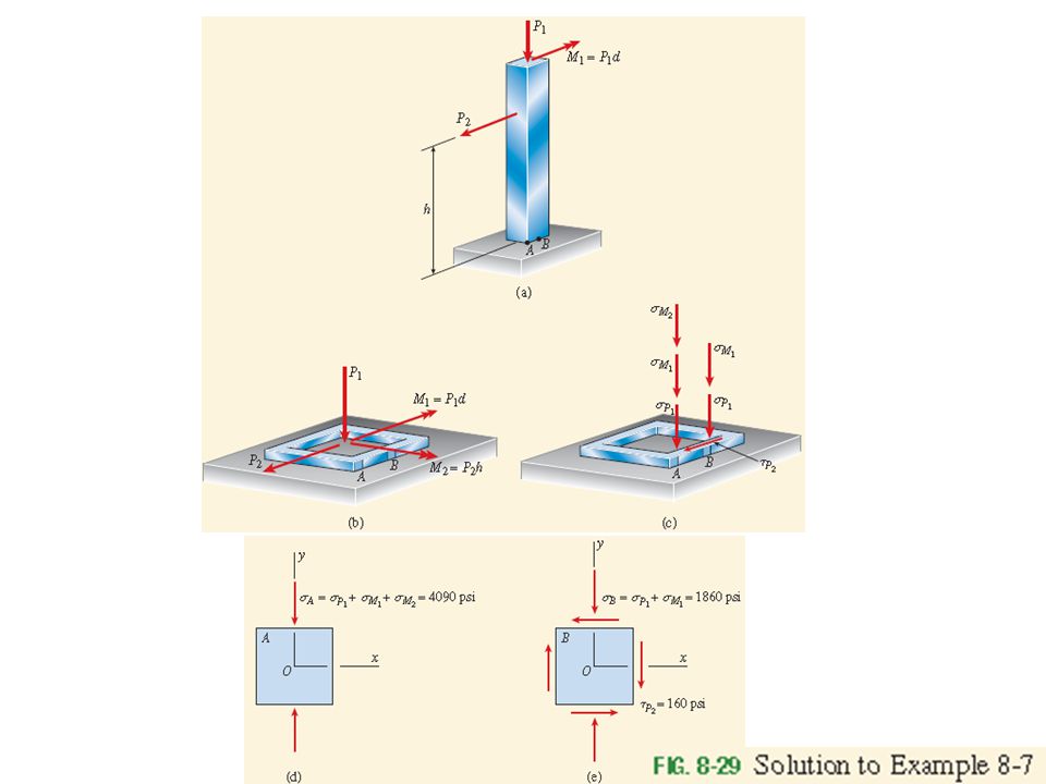
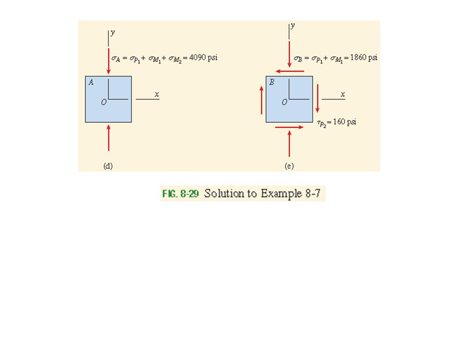
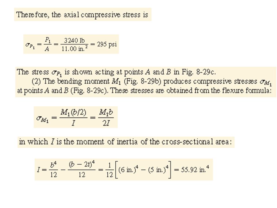
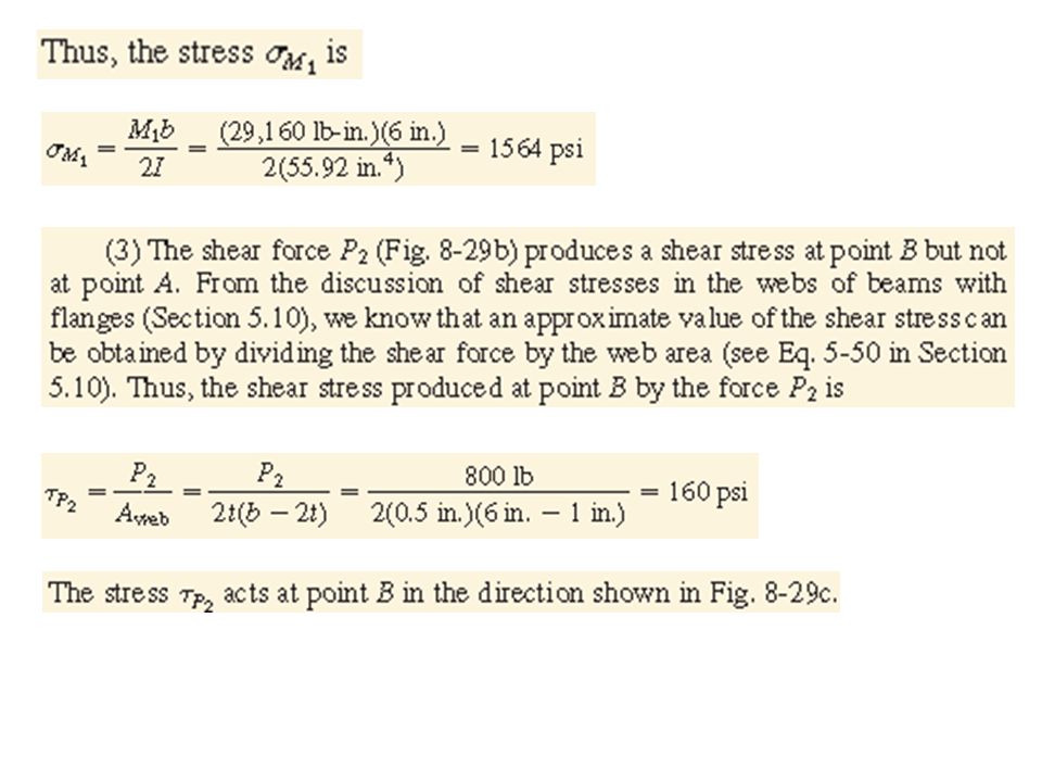
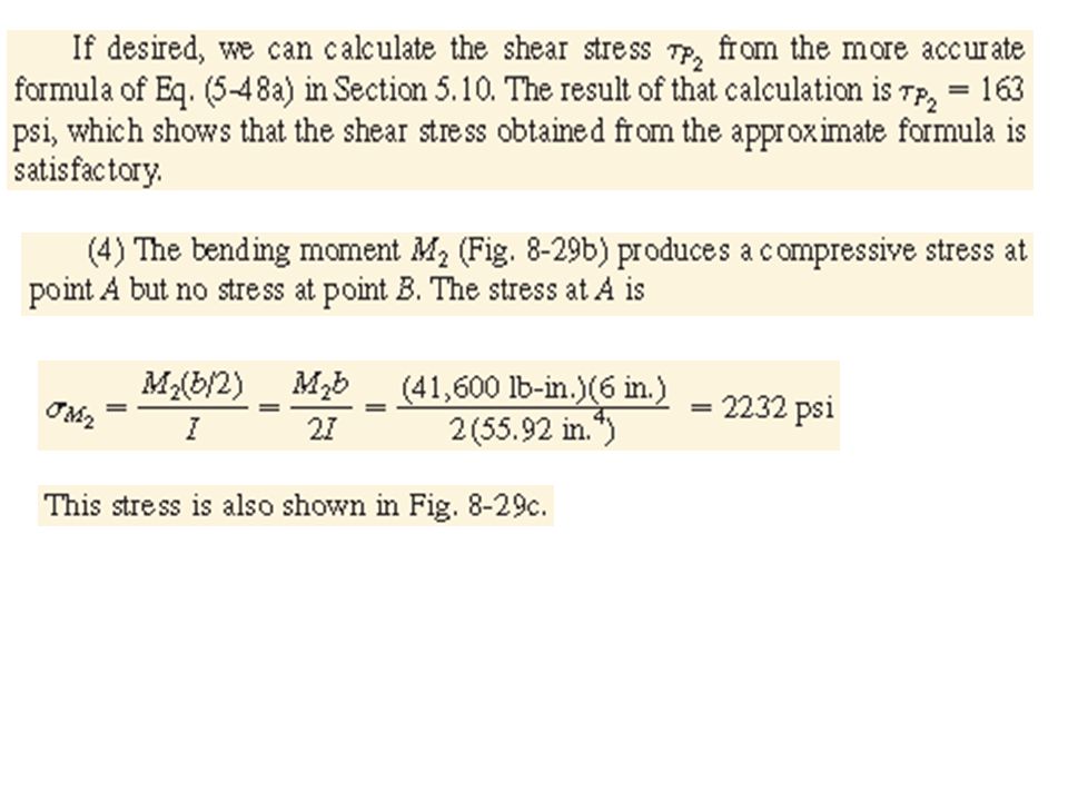
Example (GERE): A tubular post of square cross section supports a horizontal platform (Fig. 8-28). The tube has outer dimension b=6 in. and wall thickness t=0.5 in. The platform has dimensions 6.75 in. x 24.0 in. and supports a uniformly distributed load of 20 psi acting over its upper surface. The resultant of this distributed load is a vertical force P1 : This force acts at the midpoint of the platform, which is at distance d=9 in. from the longitudinal axis of the post. A second load P2=800 lb acts horizontally on the post at height h=52 in. above the base. Determine the principal stresses and maximum shear stresses at points A and B at the base of the post due to the loads P1= and P2=.

Benzer bir sunumlar


.>")


 ve BURKULMA (Buckling) M.Feridun Dengizek>")


