Sunuyu indir
Sunum yükleniyor. Lütfen bekleyiniz

1
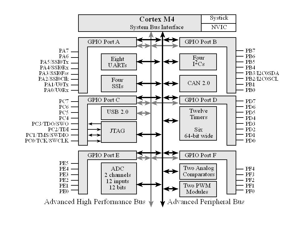
GPIO Burhan Baraklı

5
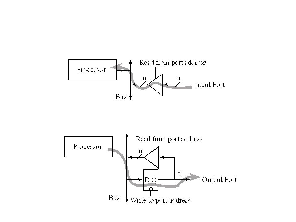
İki yönlü

6
Giriş

9
7 adımda i/o PF için 1. Portun Clock’unu aktifleştir.
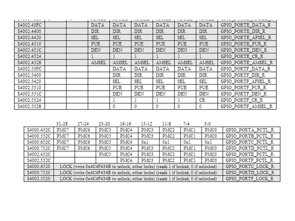
SYSCTL_RCGC2_R |= 0x ; // 1) activate clock for Port F 2. Kilitin açılması gereken pinler PC3-0, PD7, PF0 GPIO_PORTF_LOCK_R = 0x4C4F434B; // 2) unlock GPIO Port F 3. Analog girişi veya çıkışı iptal et. GPIO_PORTF_AMSEL_R = 0x00; // 3) disable analog on PF 4. GPIO fonksiyonleştirmeyi ayarla. GPIO_PORTF_PCTL_R = 0x ; // 4) PCTL GPIO on PF4-0 5. Yönü belirt input veya output. GPIO_PORTF_DIR_R = 0x0E; // 5) PF4,PF0 in, PF3-1 out 6. Geri kalan alternatif fonksiyonları kapat. GPIO_PORTF_AFSEL_R = 0x00; // 6) disable alt funct on PF7-0 7. Giriş çıkışları aktif et. GPIO_PORTF_DEN_R = 0x1F; // 7) enable digital I/O on PF4-0
 activate clock for Port F. 2. Kilitin açılması gereken pinler PC3-0, PD7, PF0 GPIO_PORTF_LOCK_R = 0x4C4F434B; // 2) unlock GPIO Port F. 3. Analog girişi veya çıkışı iptal et. GPIO_PORTF_AMSEL_R = 0x00; // 3) disable analog on PF. 4. GPIO fonksiyonleştirmeyi ayarla. GPIO_PORTF_PCTL_R = 0x ; // 4) PCTL GPIO on PF Yönü belirt input veya output. GPIO_PORTF_DIR_R = 0x0E; // 5) PF4,PF0 in, PF3-1 out. 6. Geri kalan alternatif fonksiyonları kapat. GPIO_PORTF_AFSEL_R = 0x00; // 6) disable alt funct on PF Giriş çıkışları aktif et. GPIO_PORTF_DEN_R = 0x1F; // 7) enable digital I/O on PF4-0.")
10
PA7 out SYSCTL_RCGC2_R |= 0x00000001; // 1) activate clock for Port A
delay = SYSCTL_RCGC2_R; // allow time for clock to start GPIO_PORTA_AMSEL_R &= ~0x80=0x9F // 3) disable analog on PA7 GPIO_PORTA_PCTL_R &= ~0xF ; // 4) PCTL GPIO on PA7 GPIO_PORTA_DIR_R |= 0x80; // 5) PA7 out GPIO_PORTA_AFSEL_R &= ~0x80; // 6) disable alt funct on PA7 GPIO_PORTA_DEN_R |= 0x80; // 7) enable digital I/O on PA7
 disable analog on PA7. GPIO_PORTA_PCTL_R &= ~0xF ; // 4) PCTL GPIO on PA7. GPIO_PORTA_DIR_R |= 0x80; // 5) PA7 out. GPIO_PORTA_AFSEL_R &= ~0x80; // 6) disable alt funct on PA7. GPIO_PORTA_DEN_R |= 0x80; // 7) enable digital I/O on PA7.")
11
Bit adresleme 4*2b İlgilenilen bit
PORTA nın 1,2,3 pinleriyle ilgilenelim. 0x x0008+0x x0020= 0x 0x adresi okunursa pin 1,2,3 okunur. Yada bu adrese bir data yazılırsa 1,2,3 pinlerine yazılır.

12
base address for Port A is 0x4000.4000
PORTA daki 8 biti okumak istiyorsak sabit sayımız => 0x03FC =>0x FC Diğer bir deyişle GPIO_PORTA_DATA_R gibi okuyup yazarız. Eğer 5. pin ile ilgileniyorsak 0x0080 =>> 0x ===0x #define PA5 (*((volatile unsigned long *)0x )) PA5 EQU 0x PA5 = 0x20; // make PA5 high PA5 = 0x00; // make PA5 low PA5 = PA5^0x20; // toggle PA5 Profesyonel olanı tabiki pointer kavramı
0x )) PA5 EQU 0x PA5 = 0x20; // make PA5 high. PA5 = 0x00; // make PA5 low. PA5 = PA5^0x20; // toggle PA5. Profesyonel olanı tabiki pointer kavramı.")
13
Yapılacak Ödev 1 unsigned long in,out;
int main(void){ unsigned long volatile delay; SYSCTL_RCGC2_R |= 0x08; // Port D clock delay = SYSCTL_RCGC2_R; // wait 3-5 bus cycles GPIO_PORTD_DIR_R |= 0x08; // PD3 output GPIO_PORTD_DIR_R &= ~0x01; // PD0 input GPIO_PORTD_AFSEL_R &= ~0x09; // not alternative GPIO_PORTD_AMSEL_R &= ~0x09; // no analog GPIO_PORTD_PCTL_R &= ~0x0000F00F; // bits for PD3, PD0 GPIO_PORTD_DEN_R |= 0x09; // enable PD3, PD0 while(1){ in = (GPIO_PORTD_DATA_R&0x01); // in 0 if not pressed, 1 if pressed out = (in^0x01)<<3; // out 8 if not pressed, 0 if switch pressed GPIO_PORTD_DATA_R = out; } }
{ unsigned long volatile delay; SYSCTL_RCGC2_R |= 0x08; // Port D clock. delay = SYSCTL_RCGC2_R; // wait 3-5 bus cycles. GPIO_PORTD_DIR_R |= 0x08; // PD3 output. GPIO_PORTD_DIR_R &= ~0x01; // PD0 input. GPIO_PORTD_AFSEL_R &= ~0x09; // not alternative. GPIO_PORTD_AMSEL_R &= ~0x09; // no analog. GPIO_PORTD_PCTL_R &= ~0x0000F00F; // bits for PD3, PD0. GPIO_PORTD_DEN_R |= 0x09; // enable PD3, PD0. while(1){ in = (GPIO_PORTD_DATA_R&0x01); // in 0 if not pressed, 1 if pressed. out = (in^0x01)<<3; // out 8 if not pressed, 0 if switch pressed. GPIO_PORTD_DATA_R = out; } }")
16
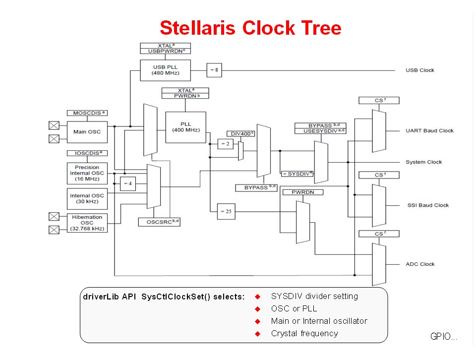
Saat Kaynakları 4 tane sat kaynağı var.
1. Hassas dahili osilatör (PIOSC) 16 MHZ+-%3 – Harici kristale ihtiyaç yoktur. 2. MOSC – Ana osilatör 3. Dahili 30 khz osilatör – Uyku modunda kullanılır. 4. Hibernation saati – hertz – real time clock source.
 16 MHZ+-%3 – Harici kristale ihtiyaç yoktur. 2. MOSC – Ana osilatör. 3. Dahili 30 khz osilatör – Uyku modunda kullanılır. 4. Hibernation saati – hertz – real time clock source.")
18
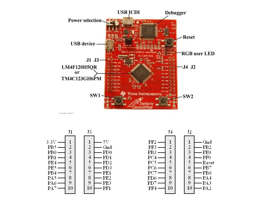
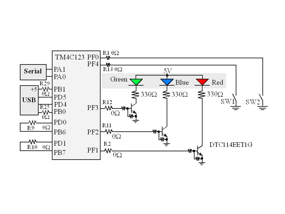
Kırmızı ledi yak ve söndür
#include "inc/lm4f120h5qr.h" void wait(void); int main() { // General-Purpose Input/Output Run Mode Clock Gating Control (RCGCGPIO), pg. 315 SYSCTL_RCGCGPIO_R |= 0x20U; // activate the clock for port f // GPIO Lock (GPIOLOCK), pg. 645 GPIO_PORTF_LOCK_R = 0x4C4F434BU; // unlock the lock register // GPIO Commit (GPIOCR), pg. 646 GPIO_PORTF_CR_R = 0xFF; // enaomble cmit for PORT F // GPIO Analog Mode Select (GPIOASMSEL), pg. 648 GPIO_PORTF_AMSEL_R = 0x00U; // disable analog functionality // GPIO Port Control (GPIOPCTL), pg. 649 GPIO_PORTF_PCTL_R = 0x U; // configure port f as GPIO // GPIO Direction (GPIODIR), pg. 624 GPIO_PORTF_DIR_R = 0x0EU; // 0xE = make PF3, PF2, and PF1 output // GPIO Alternate Function Select (GPIOAFSEL), pg. 633 GPIO_PORTF_AFSEL_R = 0x00U; // disable alternate functions // GPIO Digital Enable (GPIODEN), pg. 643 GPIO_PORTF_DEN_R = 0xFFU; // enable digital on all pins in PORTF while(1) GPIO_PORTF_DATA_R &= ~0x0E; // 0E = , so ~0E = turn off the three leds wait(); GPIO_PORTF_DATA_R |= 0x02; // turn on the red led } return 0; void wait(void) int a,i; for(i=0;i< ;i++);
; int main() { // General-Purpose Input/Output Run Mode Clock Gating Control (RCGCGPIO), pg SYSCTL_RCGCGPIO_R |= 0x20U; // activate the clock for port f. // GPIO Lock (GPIOLOCK), pg GPIO_PORTF_LOCK_R = 0x4C4F434BU; // unlock the lock register. // GPIO Commit (GPIOCR), pg GPIO_PORTF_CR_R = 0xFF; // enaomble cmit for PORT F. // GPIO Analog Mode Select (GPIOASMSEL), pg GPIO_PORTF_AMSEL_R = 0x00U; // disable analog functionality. // GPIO Port Control (GPIOPCTL), pg GPIO_PORTF_PCTL_R = 0x U; // configure port f as GPIO. // GPIO Direction (GPIODIR), pg GPIO_PORTF_DIR_R = 0x0EU; // 0xE = make PF3, PF2, and PF1 output. // GPIO Alternate Function Select (GPIOAFSEL), pg GPIO_PORTF_AFSEL_R = 0x00U; // disable alternate functions. // GPIO Digital Enable (GPIODEN), pg GPIO_PORTF_DEN_R = 0xFFU; // enable digital on all pins in PORTF. while(1) GPIO_PORTF_DATA_R &= ~0x0E; // 0E = , so ~0E = turn off the three leds. wait(); GPIO_PORTF_DATA_R |= 0x02; // turn on the red led. } return 0; void wait(void) int a,i; for(i=0;i< ;i++);")
19
Sw1-2-3 ve Led Örneği #include "inc/lm4f120h5qr.h" int main() {
// General-Purpose Input/Output Run Mode Clock Gating Control (RCGCGPIO), pg. 315 SYSCTL_RCGCGPIO_R |= 0x20U; // activate the clock for port f // GPIO Lock (GPIOLOCK), pg. 645 GPIO_PORTF_LOCK_R = 0x4C4F434BU; // unlock the lock register // GPIO Commit (GPIOCR), pg. 646 GPIO_PORTF_CR_R = 0xFF; // enable commit for PORT F // GPIO Analog Mode Select (GPIOASMSEL), pg. 648 GPIO_PORTF_AMSEL_R = 0x00U; // disable analog functionality // GPIO Port Control (GPIOPCTL), pg. 649 GPIO_PORTF_PCTL_R = 0x U; // configure port f as GPIO // GPIO Direction (GPIODIR), pg. 624 GPIO_PORTF_DIR_R = 0x0EU; // 0xE = make PF0 and PF4 input, make PF3, PF2, and PF1 output // GPIO Alternate Function Select (GPIOAFSEL), pg. 633 GPIO_PORTF_AFSEL_R = 0x00U; // disable alternate functions // GPIO Pull-Up Select (GPIOPUR), pg. 638 GPIO_PORTF_PUR_R = 0x11U; // 0x11 = enable pull up resistors on PF0(SW2) and PF4 (SW1) // GPIO Digital Enable (GPIODEN), pg. 643 GPIO_PORTF_DEN_R = 0xFFU; // enable digital on all pins in PORTF while(1) GPIO_PORTF_DATA_R &= ~0x0E; // 0E = , so ~0E = turn off the three leds switch(GPIO_PORTF_DATA_R & 0x11U) // 0x11 = case 0x00: //both switches are pressed GPIO_PORTF_DATA_R |= 0x02; // turn on the red led break; case 0x01: //SW1 is pressed, SW2 is not pressed GPIO_PORTF_DATA_R |= 0x04; // turn on the blue led case 0x10: // SW2 is pressed, SW1 is not pressed GPIO_PORTF_DATA_R |= 0x08; // turn on the green led default: // 0x11 , neither switch is pressed // don't do anything } return 0;
, pg SYSCTL_RCGCGPIO_R |= 0x20U; // activate the clock for port f. // GPIO Lock (GPIOLOCK), pg GPIO_PORTF_LOCK_R = 0x4C4F434BU; // unlock the lock register. // GPIO Commit (GPIOCR), pg GPIO_PORTF_CR_R = 0xFF; // enable commit for PORT F. // GPIO Analog Mode Select (GPIOASMSEL), pg GPIO_PORTF_AMSEL_R = 0x00U; // disable analog functionality. // GPIO Port Control (GPIOPCTL), pg GPIO_PORTF_PCTL_R = 0x U; // configure port f as GPIO. // GPIO Direction (GPIODIR), pg GPIO_PORTF_DIR_R = 0x0EU; // 0xE = make PF0 and PF4 input, make PF3, PF2, and PF1 output. // GPIO Alternate Function Select (GPIOAFSEL), pg GPIO_PORTF_AFSEL_R = 0x00U; // disable alternate functions. // GPIO Pull-Up Select (GPIOPUR), pg GPIO_PORTF_PUR_R = 0x11U; // 0x11 = enable pull up resistors on PF0(SW2) and PF4 (SW1) // GPIO Digital Enable (GPIODEN), pg GPIO_PORTF_DEN_R = 0xFFU; // enable digital on all pins in PORTF. while(1) GPIO_PORTF_DATA_R &= ~0x0E; // 0E = , so ~0E = turn off the three leds. switch(GPIO_PORTF_DATA_R & 0x11U) // 0x11 = case 0x00: //both switches are pressed. GPIO_PORTF_DATA_R |= 0x02; // turn on the red led. break; case 0x01: //SW1 is pressed, SW2 is not pressed. GPIO_PORTF_DATA_R |= 0x04; // turn on the blue led. case 0x10: // SW2 is pressed, SW1 is not pressed. GPIO_PORTF_DATA_R |= 0x08; // turn on the green led. default: // 0x11 , neither switch is pressed. // don t do anything. } return 0;")
20
Api Örneği Blink 1 Step1 - Set up System Clock
SysCtlClockSet(SYSCTL_SYSDIV_5|SYSCTL_USE_PLL|SYSCTL_XTAL_16MHZ|SYSCTL_OSC_MAIN); We need to generate a system clock of 40 MHz. We know that the input clock frequency after system prescale is 200 MHz SYSCTL_USE_PLL - this macro is used to specify that we are using the PLL to generate the 400 MHz clock frequency. SYSCTL_XTAL_16MHz - This says to the uC that we give the input to the PLL from an external crystal(XTAL) of frequency 16 MHz. SYSCTL_OSC_MAIN - This denotes that we are using an external main oscillator ( Again represents the 16 MHz crystal ). Now we know that all these are to be done together, and that is the reason why we logically OR all the macros. ##NOTE - Generally inside a function whose name starts with SysCtl, the macro names will start with "SYSCTL_". This will help you in selecting the correct macro most of the time.
; We need to generate a system clock of 40 MHz. We know that the input clock frequency after system prescale is 200 MHz. SYSCTL_USE_PLL - this macro is used to specify that we are using the PLL to generate the 400 MHz clock frequency. SYSCTL_XTAL_16MHz - This says to the uC that we give the input to the PLL from an external crystal(XTAL) of frequency 16 MHz. SYSCTL_OSC_MAIN - This denotes that we are using an external main oscillator ( Again represents the 16 MHz crystal ). Now we know that all these are to be done together, and that is the reason why we logically OR all the macros. ##NOTE - Generally inside a function whose name starts with SysCtl, the macro names will start with SYSCTL_ . This will help you in selecting the correct macro most of the time.")
21
SysCtlPeripheralEnable(SYSCTL_PERIPH_GPIOF);
Step 2 - Enable the GPIO SysCtlPeripheralEnable(SYSCTL_PERIPH_GPIOF); SysCtlPeripheralEnable(SYSCTL_PERIPH_GPIOA); Step 3 - Setting The Data direction Consider that we want to configure the PIN 6 of GPIO PORT F as output. This can be done as shown below : GPIOPinTypeGPIOOutput(GPIO_PORTF_BASE, GPIO_PIN_6); Let us take another example. Consider that we want to configure the PIN5 and 7 of PORTA and PIN3 of PORTB also as input. This can be done as shown below : GPIOPinTypeGPIOInput(GPIO_PORTA_BASE, GPIO_PIN_5|GPIO_PIN_7); GPIOPinTypeGPIOInput(GPIO_PORTB_BASE, GPIO_PIN_3);
; SysCtlPeripheralEnable(SYSCTL_PERIPH_GPIOA); Step 3 - Setting The Data direction. Consider that we want to configure the PIN 6 of GPIO PORT F as output. This can be done as shown below : GPIOPinTypeGPIOOutput(GPIO_PORTF_BASE, GPIO_PIN_6); Let us take another example. Consider that we want to configure the PIN5 and 7 of PORTA. and PIN3 of PORTB also as input. This can be done as shown below : GPIOPinTypeGPIOInput(GPIO_PORTA_BASE, GPIO_PIN_5|GPIO_PIN_7); GPIOPinTypeGPIOInput(GPIO_PORTB_BASE, GPIO_PIN_3);")
22
Step 4 - Writing data into the GPIO
GPIOPinWrite(GPIO_PORTF_BASE, GPIO_PIN_1, 2); //Lights the RED LED GPIOPinWrite(GPIO_PORTF_BASE, GPIO_PIN_2, 4); //Lights the BLUE LED GPIOPinWrite(GPIO_PORTF_BASE, GPIO_PIN_3, 8); //Lights the GREEN LED GPIOPinWrite(GPIO_PORTF_BASE, GPIO_PIN_1|GPIO_PIN_2|GPIO_PIN_3, 14); //Lights the ALL LEDs Step 5 - Delay loop void delay_ms(int del) //generates delay in milliseconds { del = (SysCtlClockGet()/3.0)*del/1000.0; SysCtlDelay(del); }
; //Lights the RED LED GPIOPinWrite(GPIO_PORTF_BASE, GPIO_PIN_2, 4); //Lights the BLUE LED GPIOPinWrite(GPIO_PORTF_BASE, GPIO_PIN_3, 8); //Lights the GREEN LED GPIOPinWrite(GPIO_PORTF_BASE, GPIO_PIN_1|GPIO_PIN_2|GPIO_PIN_3, 14); //Lights the ALL LEDs. Step 5 - Delay loop. void delay_ms(int del) //generates delay in milliseconds { del = (SysCtlClockGet()/3.0)*del/1000.0; SysCtlDelay(del); }")
23
#include <inc/hw_types. h> #include <inc/hw_memmap
#include <inc/hw_types.h> #include <inc/hw_memmap.h> #include <driverlib/gpio.h> #include <driverlib/sysctl.h> void delay_ms(int del) { del = (SysCtlClockGet()/3.0)*del/1000.0; SysCtlDelay(del); } int main(void) { SysCtlClockSet(SYSCTL_SYSDIV_5|SYSCTL_USE_PLL|SYSCTL_XTAL_16MHZ|SYSCTL_OSC_MAIN); /*Enabling the system clock for GPIO PORT F. We must do this for every peripheral that we use */ SysCtlPeripheralEnable(SYSCTL_PERIPH_GPIOF); GPIOPinTypeGPIOOutput(GPIO_PORTF_BASE, GPIO_PIN_1|GPIO_PIN_2|GPIO_PIN_3); while(1) { GPIOPinWrite(GPIO_PORTF_BASE, GPIO_PIN_1, 2); delay_ms(1000); // 1 second delay GPIOPinWrite(GPIO_PORTF_BASE, GPIO_PIN_1, 0); //explicitly turning off the led GPIOPinWrite(GPIO_PORTF_BASE, GPIO_PIN_2, 4); delay_ms(1000); GPIOPinWrite(GPIO_PORTF_BASE, GPIO_PIN_2, 0); GPIOPinWrite(GPIO_PORTF_BASE, GPIO_PIN_3, 8); delay_ms(1000); GPIOPinWrite(GPIO_PORTF_BASE, GPIO_PIN_3, 0); } }
 { del = (SysCtlClockGet()/3.0)*del/1000.0; SysCtlDelay(del); } int main(void) { SysCtlClockSet(SYSCTL_SYSDIV_5|SYSCTL_USE_PLL|SYSCTL_XTAL_16MHZ|SYSCTL_OSC_MAIN); /*Enabling the system clock for GPIO PORT F. We must do this for every peripheral that we use */ SysCtlPeripheralEnable(SYSCTL_PERIPH_GPIOF); GPIOPinTypeGPIOOutput(GPIO_PORTF_BASE, GPIO_PIN_1|GPIO_PIN_2|GPIO_PIN_3); while(1) { GPIOPinWrite(GPIO_PORTF_BASE, GPIO_PIN_1, 2); delay_ms(1000); // 1 second delay GPIOPinWrite(GPIO_PORTF_BASE, GPIO_PIN_1, 0); //explicitly turning off the led GPIOPinWrite(GPIO_PORTF_BASE, GPIO_PIN_2, 4); delay_ms(1000); GPIOPinWrite(GPIO_PORTF_BASE, GPIO_PIN_2, 0); GPIOPinWrite(GPIO_PORTF_BASE, GPIO_PIN_3, 8); delay_ms(1000); GPIOPinWrite(GPIO_PORTF_BASE, GPIO_PIN_3, 0); } }")
24
Button ve Led Örneği int main(void) {
SysCtlClockSet(SYSCTL_SYSDIV_5|SYSCTL_USE_PLL|SYSCTL_XTAL_16MHZ|SYSCTL_OSC_MAIN); SysCtlPeripheralEnable(SYSCTL_PERIPH_GPIOF); // Set PF4(SW_1) as input GPIOPinTypeGPIOInput(GPIO_PORTF_BASE, GPIO_PIN_4); /* * As it is a switch, we should use a pull up resistor. * Stellaris can be configured with various pull up/down resistors based on the drive strength(current) specified. * Refer to the Stellaris API page number 124 for more configurations * Link: */ GPIOPadConfigSet(GPIO_PORTF_BASE, GPIO_PIN_4, GPIO_STRENGTH_4MA, GPIO_PIN_TYPE_STD_WPU); //Set PF1(RED LED) as output GPIOPinTypeGPIOOutput(GPIO_PORTF_BASE, GPIO_PIN_1); //Turn of the LED GPIOPinWrite(GPIO_PORTF_BASE, GPIO_PIN_1, 0); while(1) //Check whether the button is pressed. if(!GPIOPinRead(GPIO_PORTF_BASE, GPIO_PIN_4)) //Set PF1 as high. 2 ~ 0b >mask PF1 GPIOPinWrite(GPIO_PORTF_BASE, GPIO_PIN_1, 2); else }
; SysCtlPeripheralEnable(SYSCTL_PERIPH_GPIOF); // Set PF4(SW_1) as input. GPIOPinTypeGPIOInput(GPIO_PORTF_BASE, GPIO_PIN_4); /* * As it is a switch, we should use a pull up resistor. * Stellaris can be configured with various pull up/down resistors based on the drive strength(current) specified. * Refer to the Stellaris API page number 124 for more configurations. * Link: */ GPIOPadConfigSet(GPIO_PORTF_BASE, GPIO_PIN_4, GPIO_STRENGTH_4MA, GPIO_PIN_TYPE_STD_WPU); //Set PF1(RED LED) as output. GPIOPinTypeGPIOOutput(GPIO_PORTF_BASE, GPIO_PIN_1); //Turn of the LED. GPIOPinWrite(GPIO_PORTF_BASE, GPIO_PIN_1, 0); while(1) //Check whether the button is pressed. if(!GPIOPinRead(GPIO_PORTF_BASE, GPIO_PIN_4)) //Set PF1 as high. 2 ~ 0b >mask PF1. GPIOPinWrite(GPIO_PORTF_BASE, GPIO_PIN_1, 2); else. }")
25
Ödev 2 – HWREG Hwreg nedir? Bir örnek? Nasıl kullanılır?

26
Ödev 3 4 ledli - kit arabasının gidip gelen ledlerini breadbordda yapınız. Sw2 butonuna basınca ledler arasındaki bekleme süresi uzasın Sw1 butonuna basınca ledler arasındaki süre kısalsın. Bekleme süresini istediğiniz şekilde yazabilirsiniz. For döngüsü yada bekleme fonksiyonu? Aynı örneği API fonksiyonları olmadan yapın? Aynı örneği API fonksiyonlarını kullanmadan bit kaydırma operatörü ile gerçekleyin?

27
Bütün ödevler Flashbelleğe atın!
Pazartesi Saat 15:00’a kadar Burhan Baraklı’nın odasına teslim edin.

Benzer bir sunumlar


 ve tarafınızdan belirlenen Şifre ile giriş yapılır; You can have access to Student.>")
 problemleri (Matching and Assignment problems)>")

 2 friends... you'll have 3 years of good luck!!!>")


.>")

>")


>")


 (Yrd. Doç. Dr. Deniz Dal)>")