Sunuyu indir
Sunum yükleniyor. Lütfen bekleyiniz

1
Metallere Plastik Şekil Verme
Haddeleme (Rolling)
")
2
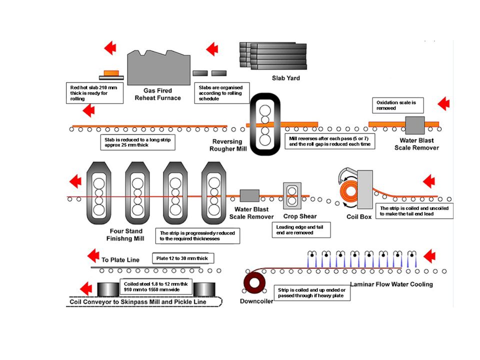
Haddeleme Amaç; Sıcak ve soğuk olarak ikiye ayrılabilen farklı tipte haddeleme prosesleri Haddeleme prosesindeki matematiksel yaklaşımlara giriş Haddelemede oluşabilecek hatalar ve çözümleri Tanım: İş parçasını, eksenleri etrafında dönen silindirler (merdaneler) arasından geçirerek uygulanan basma kuvvetleri etkisiyle plastik şekil verme işlemine haddeleme denir. Haddeleme, son ürün kontrolü ve yüksek üretim kapasitesi sağlayan çok geniş kullanıma sahip şekillendirme prosesidir.
 arasından geçirerek uygulanan basma kuvvetleri etkisiyle plastik şekil verme işlemine haddeleme denir. Haddeleme, son ürün kontrolü ve yüksek üretim kapasitesi sağlayan çok geniş kullanıma sahip şekillendirme prosesidir.")
3
Haddeleme Haddeleme Prosesi, temel olarak sıcak haddeleme ve soğuk haddeleme olarak ikiye ayrılır. Sıcak haddeleme; Başlangıçta ingotların blum,slab ve kütüklere dönüştürülmesi genellikle sıcak haddelemeyle yapılır. Soğuk haddeleme; Kaliteli yüzey ve hassas boyut kontrolü, yükseltilmiş mekanik özellikli saç, bant ve folyoların üretiminde büyük rol oynar.

4
Haddeleme Sıvı metalin dökme demir kokillere doldurulup katılaşmaya bırakılmasıyla ingotlar, ingotların sıcak haddelenmesiyle ilk ürün olarak blum, slab ve kütükler elde edilir. Blum, slab ve kütüklerin tekrar haddelenmesiyle profil, ray, çubuk, saç ve boru gibi ürünler elde edilir.

5
Haddeleme

6
Haddeleme

7
Metal haddelemenin temelleri
Hipotez (varsayım); 1- Merdane ve metal arasındaki temas yayı çemberin bir kısmıdır. 2-Sürtünme katsayısı (µ) teoride sabittir, ancak gerçekte temas yayı boyunca değişmektedir. 3-Haddeleme süresince metalin plastik deformasyona uğradığı kabul ediliyor. 4-Haddelemeden önce ve sonra metal hacmi sabittir. Pratikte ise yapı içerisinde var olan porların kapanmasıyla hacimde çok küçük azalma olmaktadır. 5-Merdanelerin hızı sabit kabul ediliyor. 6-Metal sadece haddeleme yönünde uzuyor ve malzeme eninde genişleme yok. 7-Haddeleme yönüne dik kesit alanında distorsiyon yok.
; 1- Merdane ve metal arasındaki temas yayı çemberin bir kısmıdır. 2-Sürtünme katsayısı (µ) teoride sabittir, ancak gerçekte temas yayı boyunca değişmektedir. 3-Haddeleme süresince metalin plastik deformasyona uğradığı kabul ediliyor. 4-Haddelemeden önce ve sonra metal hacmi sabittir. Pratikte ise yapı içerisinde var olan porların kapanmasıyla hacimde çok küçük azalma olmaktadır. 5-Merdanelerin hızı sabit kabul ediliyor. 6-Metal sadece haddeleme yönünde uzuyor ve malzeme eninde genişleme yok. 7-Haddeleme yönüne dik kesit alanında distorsiyon yok.")
8
Yassı Ürünlerin haddelenmesi
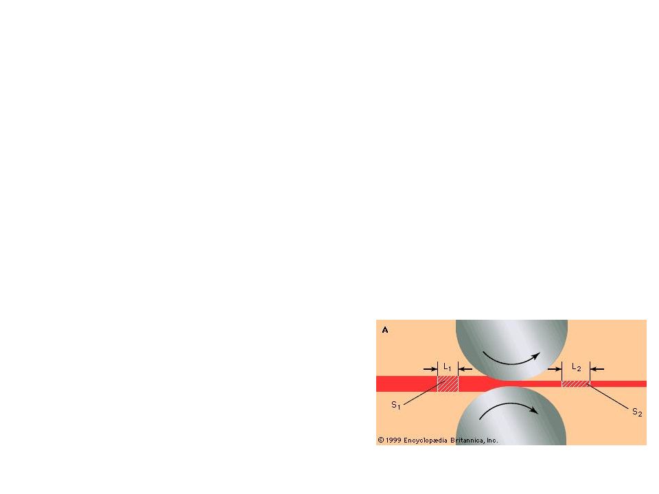
ho kalınlığındaki saç metal v0 hızı ile xx giriş düzlemindeki merdaneye giriyor. Merdane aralığından geçiyor ve vf hızında azaltılmış hf kalınlığı ile yy çıkış düzleminden çıkıyor. Kalınlıkta genişleme olmadığı varsayımı ile metaldeki dikey basınç haddeleme yönündeki uzamaya aktarılıyor. Herhangi bir zaman diliminde hacim sabit olduğu için; ho > hf olduğunda , v0 < vf olur Dolayısıyla metal saçın hızı girişten çıkışa doğru sürekli artmaktadır.

9
Yassı Ürünlerin haddelenmesi
Merdanenin çevresel hızının yatay bileşeni Metal saç hızı ve Merdanenin yatay bileşen hızı arasındaki eşitlikler; Metal saçın hızının (V) merdanenin yatay hız (Vm.y) bileşenine eşit olduğu (V= Vm.y ) düzleme nötr düzlem denilmektedir. V= Vm.y
 merdanenin yatay hız (Vm.y) bileşenine eşit olduğu (V= Vm.y ) düzleme nötr düzlem denilmektedir. V= Vm.y.")
10
1)Radyal kuvvet 2)Teğetsel sürtünme kuvveti
Yassı Ürünlerin haddelenmesi Merdane ve saç arasındaki temas yüzeyi boyunca metal üzerine etkiyen 2 kuvvet var: 1)Radyal kuvvet 2)Teğetsel sürtünme kuvveti
Radyal kuvvet 2)Teğetsel sürtünme kuvveti.")
11
Haddeleme Kuvvetleri Haddeleme kuvvetlerinin düşürülmesi için
Sürtünmeyi katsayısını azaltmak Merdane Çapını azaltmak Sıcaklığı artırmak Saça σb ve σf çekme gerilmeleri uygulamak besleme ve sarma merdaneleri

12
Çift yönlü(tersinir) ikili düzen:
Merdane Düzenleri Çift yönlü(tersinir) ikili düzen: Malzeme haddelendikten sonra, merdaneler üzerinden dolaştırılmadan tekrar haddelemek için yön değiştirilir. 2. hadde de merdaneler arası mesafe düşürülür. Tek yönlü ikili düzen: En basit merdane düzenidir. Dörtlü düzen: Haddeleme kuvvetinin düşürülmesi için merdane çapı düşürülür. Ancak çapla beraber dayanım ve rijitlik azaldığından büyük çaplı merdaneler ile desteklenir. Destek merdaneleri iş merdanelerinin dikey doğrultuda eğilmelerini önler. Üçlü düzen: Üç merdane üst üste dizilmiştir ve malzeme 2 yönde de haddelenebilir. Alttaki ve üstteki merdaneler dönme kuvveti uyguluyor ancak ortadaki sürtünmeyle döndürülüyor.
 ikili düzen: Malzeme haddelendikten sonra, merdaneler üzerinden dolaştırılmadan tekrar haddelemek için yön değiştirilir. 2. hadde de merdaneler arası mesafe düşürülür. Tek yönlü ikili düzen: En basit merdane düzenidir. Dörtlü düzen: Haddeleme kuvvetinin düşürülmesi için merdane çapı düşürülür. Ancak çapla beraber dayanım ve rijitlik azaldığından büyük çaplı merdaneler ile desteklenir. Destek merdaneleri iş merdanelerinin dikey doğrultuda eğilmelerini önler. Üçlü düzen: Üç merdane üst üste dizilmiştir ve malzeme 2 yönde de haddelenebilir. Alttaki ve üstteki merdaneler dönme kuvveti uyguluyor ancak ortadaki sürtünmeyle döndürülüyor.")
13
Merdane Düzenleri Dörtlü düzen merdane sistemlerinde iş merdanelerinin dikey doğrultuda eğilmeleri destek merdaneleri ile önlenebilmektedir. Fakat iş merdanelerinin yatay doğrultuda da eğilebileceği için, dörtlü düzende iş merdanelerinin çapı belirli bir değerden küçük alınamaz. İş merdanelerini daha da küçültebilmek için 4, 10, 18 destekli merdane sistemleri geliştirilmiştir. Çok rijit olan 20 li tezgahlar yüksek dayanımlı ince saçların dar toleranslarla soğuk haddelenmesine özellikle uygulanır. Bu tezgahlarda dayanım, rijitlik ve aşınma gibi faktörler göz önüne alınarak WC den üretilen iş merdaneleri kullanılır.

14
Merdane Düzenleri Sadece besleme ve sarma işi yapmazlar
Birkaç hadde tezgahının ard arda sıralandığı soğuk hadde tezgahlarına tandem hadde tezgahı denmektedir. Genellikle rulo halinde saçların haddelendiği tezgahta bir merdaneden çıkan saçın hızı ile girdiği merdanenin dönme hızı ayarlanmalıdır. Boşaltma ve sarma bobinlerinin hızları ayarlanarak saca uygulanan yatay çekme kuvvetleri vasıtasıyla haddeleme kuvveti azaltılabilir. Her bir planet merdane hemen hemen aynı inceltme sağlar Toplam incelme her bir planet merdane çiftinin küçük azalmalarının toplamı kadardır. Dolayısıyla bir beslemede büyük miktar incelme sağlanır. Besleme rulosu giriş kuvvetini sağladığı için son yüzey kalitesi yüksektir. Planet düzende içteki büyük çaplı destek merdaneleri etrafında dıştaki küçük iş merdaneleri döner. Geleneksel sıcak haddeleme tezgahında bir pasoda en çok %30-40 azaltılabilirken, planet hadde ile bu değer %90 lara kadar çıkabilmektedir.

15
Çubuk ve Profillerin Haddelenmesi
Çeşitli kesitte (dairesel, dörtgen vb.) çubuklar, profiller (I,U kesitli), köşebentleri, otomobil parçaları, çelik borular, kapı ve pencere çerçeveleri, demiryolu rayları, tavan panelleri, ev gereçleri, metal mobilyalar….
 çubuklar, profiller (I,U kesitli), köşebentleri, otomobil parçaları, çelik borular, kapı ve pencere çerçeveleri, demiryolu rayları, tavan panelleri, ev gereçleri, metal mobilyalar….")
16
Çubuk ve Profillerin Haddelenmesi
Pasoların yan yüzeyleri merdane eksenine dik olmayıp eğiktir. Kalibrenin yan yüzeylerinin eğimli yapılması; İş parçasının giriş-çıkışını kolaylaştırır Aşınmayı azaltır Katmer kusurunun oluşmasını önler İş parçası küçük çaplı merdaneye doğru döner. Çapı büyük olan merdanenin konumuna göre alt ezme ya da üst ezme durumu vardır. Ezmenin tipine bağlı olarak çıkış yolluğu yerleştirilir. Son pasoda ise heterojen iç gerilmelere neden olmamak için merdane çapları eşit olmalıdır.

17
Her kademede kesit azalması %10-30 arasında
Kutu Paso Serileri Blum ve kütüklerin haddelenerek kare, dairesel basit çubukların üretimi Her kademede kesit azalması %10-30 arasında Çubukların haddelenerek kesitlerinin küçültülmesi işlemlerinde ve bitmiş kare kesitlerin elde edilmesinde kullanılır. Oval-kare paso serileri, en az paso adetiyle en fazla kesit azalması sağlayan serilerdir. Büyük ekseniyle küçük ekseni arasındaki oran arttıkça kesit azalması ya da uzama da artar.

18
Üretim Aşamaları İngot döküm Gas porozitesi Gas porozitesi
Büzülme hataları Segregasyon vb

19
Üretim Aşamaları

20
Üretim Aşamaları X-Ray sensörler

21
Blum, slab, kütük ve büyük kesitlerin haddelenmesi
Yuvarlak kesitlerin, kare kesitlerin, lama ve bantların, köşebentlerin haddelenmesinde kullanılan paso serileri

22
Levha ve Saçların Haddelenmesi
Slabların sıcak haddelenmesiyle elde edilen saçlar. Soğuk haddelemeden önce dekapaj yapılarak yüzey temizlenir ve gerekirse kotrollü atmosferde pekleşmenin etkilerini gidermek için yeniden kristallenme uygulanır. Levhaların soğuk haddelenmesiyle elde edilen saçlar. (galvanizlenmiş) Soğuk haddelemeden önce dekapaj yapılarak yüzey temizlenir ve gerekirse kotrollü atmosferde pekleşmenin etkilerini gidermek için yeniden kristallenme uygulanır.
 Soğuk haddelemeden önce dekapaj yapılarak yüzey temizlenir ve gerekirse kotrollü atmosferde pekleşmenin etkilerini gidermek için yeniden kristallenme uygulanır.")
23
Hadde Ürünlerinde Kusurlar

24
Hadde Ürünlerinde Kusurlar
Haddeleme aralığı bütün merdane boyunca eşit olmalı. Haddeleme hızı düzlüğe çok hassas bağlıdır. Lokal olarak de 1 boyut değişimi farkı dalgalılığa neden olur. Dalgalanma merdanelerin düşey doğrultuda eğilmesi sonucu oluşur.

25
Hadde Ürünlerinde Kusurlar
Yeteri kadar sünek ise Kalınlık kenarlarda orta kısma kıyasla daha düşüktür dolayısıyla kenarların orta kısımdan fazla uzaması fakat serbestçe yayılamaması kenarlardaki dalgalanmaya yol açar. Çekme gerilmesi Sünek değil ise Basma gerilmesi Basma gerilmesi

26
Hadde Ürünlerinde Kusurlar
Yeteri kadar sünek ise Sürtünme ortadaki kısımda kenarlara kıyasla daha fazla olduğundan orta kısım sadece boyuna uzama gösterirken kenar kısımlar az da olsa enlemesine uzama da gösterirler. Bu eş kesitte orta kısmın kenar kısımlara oranla daha fazla uzamasına neden olur. Basma gerilmesi Çekme gerilmesi Çekme gerilmesi Sünek değil ise

27
Hadde Ürünlerinde Kusurlar
Saç haddeleme kusurlarının önlenmesi; Oluşan merdana sehimine göre ters yönde bombe verilmiş merdaneler kullanmak. Ters yönde ve farklı tahrik kuvvetleri uygulayan merdane düzenleri kullanmak;

28
Konik yardımcı merdaneler halkanın yüksekliğini ayarlar
Halka Haddeleme Ana merdane et kalınlığındaki azalmaya neden olarak çemberin çapında artış sağlar Konik yardımcı merdaneler halkanın yüksekliğini ayarlar Jet motorları için büyük halkalar, rulmanlı yatak bilezikleri tipik uygulama örnekleridir.

29
Ovalama Ovalama ile açılacak dişe göre uygun çaplı silindirik malzeme düzlemsel veya silindirik takımlar arasından geçirilir. Talaşlı kaldırmadan üstünlükleri; Yüksek üretim hızı Malzeme kaybı olmaması Soğuk deformasyon nedeniyle mekanik özelliklerin yükselmesi Yüzey düzgünlüğü Yüzeydeki basma gerilmeleriyle yorulma ömrünün artması Talaşlı Ovalama

30
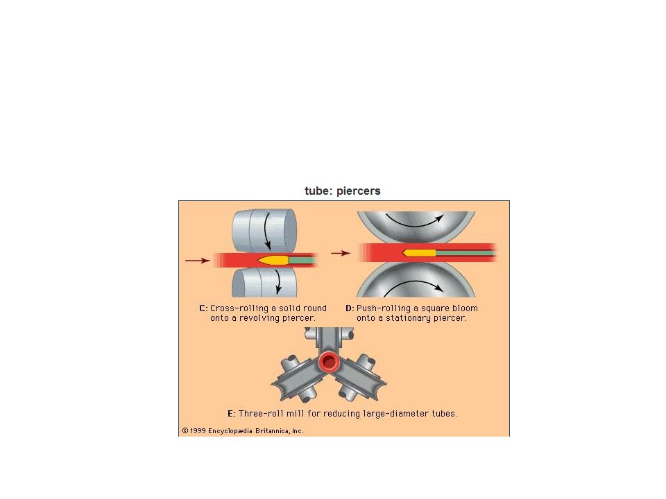
Dikişsiz Boru Üretimi Mannesmann yöntemi
İş merdanelerinin eksenleri parallel düzlemler içinde olup malzemenin ekseniyle açı yapar. Hammadde sıcak olarak merdaneler arasına sürüldüğünde uygulanan basınç, ikincil çekme gerilmeleriyle çatlak oluşumuna yol açar. Boru uzunluğu malafa ile sınırlıdır Kalın cidarlı borular Hassas boyut kontrolü olmayan borular Et kalınlığı ince boru üretimi için ön şekillendirme görevi görebilir.

31
Mannesman yöntemiyle üretilmiş borulara uygulanır.
Boruların Haddelenmesi Mannesman yöntemiyle üretilmiş borulara uygulanır. Stiefel yöntemi:merdaneler arasından dönerek ilerleyen borunun et kalınlığı azalır ve çapı artar ancak uzunluk sabit kalır.(Sıcak olarak uygulanır.) İş merdanelerini üzerinde birden çok kalibre vardır. Genelde bir kalibre ve bir malafa kullanılır. Boru merdaneler arasından bir kez geçtikten sonra 90 ̊döndürülerek bir daha haddelenir.(Sıcak olarak uygulanır.)
 İş merdanelerini üzerinde birden çok kalibre vardır. Genelde bir kalibre ve bir malafa kullanılır. Boru merdaneler arasından bir kez geçtikten sonra 90 ̊döndürülerek bir daha haddelenir.(Sıcak olarak uygulanır.)")
32
Demiryolu Tekerlekleri ve Kasnakların Haddelenmesi
1-sıcak hammadde preste dövülerek delinir. 2-preste şekillendirilir 3-merdaneli tezgahta haddelenir 4-preste dövülür.

33
The two-high mill was the first and simplest but production rates tended to be low because of the time lost in returning the metal to the front of the mill. This obviously led to the reversing two-high mill where the metal could be rolled in both directions. Such a mill is limited in the length that it can handle, and if the rolling speed is increased, the output is almost unchanged because of the increased time spent in reversing the rotation at each pass. This sets an economic maximum of about 10 meters. The next obvious development was the three-high mill, which has the advantages of both the two high reversing and non-reversing mills. Such a mill must, of course, have elevating tables on both sides of the rolls. The roll gap on a three-high mill cannot be adjusted between passes, therefore grooves or passes must be cut into the roll face to achieve different pass reductions. All three kinds of mill suffer from the disadvantage that all stages of rolling are carried out on the same rolled surface and the surface quality of the product tends to be low. Roll changes on such mills are relatively frequent and time consuming. This type of mill is therefore used for primary rolling where rapid change of shape is required, even at the expense of surface quality. Four-high mills are a special case of two-high, and in an attempt to lower the rolling load, the work roll diameter is decreased. There is, however, a risk of roll bending which is avoided by supporting the small work rolls by larger backing rolls. The backing roll diameter cannot be greater than about 2-3 times that of the work rolls, and as the work roll diameter is decreased more and more (to accommodate processes with exceedingly high rolling loads) the size of the backing rolls must also decrease. A point is reached when the backing rolls themselves begin to bend and must be supported hence the ultimate design - the cluster mill. The principal criticism of the traditional mill is this tendency for roll bending due to its inherent design - the beam principle. Sendzimir proposed a design which eliminated this limitation based on the castor principle where the work roll is supported over ali its face by an array of backing rolls. This principle can be applied to much mills and an installation for rolling stainless steel 1600 mm wide is fitted with work rolls 85 mm diameter. Continuous rolling mills can be classified according to the arrangement of stands or passes. These are in line in a continuous mill and line abreast in a looping or cross-country mill. Looping and cross-country mills require the workpiece to be bent or turned between stands and are used therefore for rolling rods, rails or sections. Continuous mills are used for plates, strip or sheets. They all require a large capital outlay and are only justified when a large demand for the product is guaranteed. It is possible to derive an expression for this friction force. Pressure acts radially on the ends of this element, and if the element is located between the point of entry and the neutral point a frictional force acts toward the neutral point. The radial pressure has a horizontal component which tends to reject the metal and prevent it from entering the rolls, whilst the friction force has a horizontal component dragging the metal inward. Whether the metal passes through the rolls depends upon the values of the two horizontal force components. Primary rolling is a process where large maximum reductions are required in order that the metal can be deformed quickly and cheaply. Such mills have large diameter rolls with surfaces that are roughened or ragged to increase the coefficient of friction. The rolling load can be minimized by making the radius as small as possible and the roll surface as smooth as possible. This principle is used in the design of cluster mills which are used extensively for foil rolling and consist of small work rolls supported by larger back-up rolls to prevent bending. Even with such mills the rolling loads can still be excessive and recourse is made to devices which apply front and back tension to the metal being rolled. Foil rolling and finishing mills are generally very different from primary mills which as already seen tend to use large diameter rolls with roughened surfaces. It is an essential of metal-deformation processes that the tool is only loaded elastically, while the workpiece is flowing plastically. This elastic deformation is generally so small that it can be ignored, but this is not the case in rolling. There are two reasons. One is that rolling loads and stresses can be very large, especially when the workpiece is thin and work-hardened. The other is that the tool in rolling comprises the whole mill-rolls and housing with overall dimensions measurable in meters. This combination can result in very large strains due to elastic deformation divided between mill stand extension "mill spring", roll flattening and roll bending. Roll flattening. The workpiece passing between a pair of rolls is compressed by the radial stress in them, but the reaction is transferred to the mill bearings and housing, which are capable of only limited yield because of their large dimensions. If an attempt is made to compress thin hard material further, the reaction becomes so large that the rolls deform elastically and the radius of curvature of the arc of contact is increased. The extent of this flattening depends on the magnitude of the reaction stress and the elastic constants of the rolls. Roll flattening has another effect in that for a given mill there is a minimum gauge below which it is not possible to roll. Any attempt to do so results in greater deformation of the rolls, without any plastic deformation of the strip. With thin gauges as already seen the friction hill becomes very large producing reaction stresses in the arc of contact which exceed the yield stress of the rolls, therefore it is easier to deform the rolls than the metal. As long as the mill is running the rolls will remain circular, but if the load is not removed when it is stopped, deformation will take place to flatten the surface over the area of contact between the rolls. Attempts to avoid or limit roll bending have involved ways of decreasing the rolling load. This has resulted in small work rolls and four-high mills. But even with these mills a certain amount of roll bending still occurs and is accommodated by cambering the rolls, i.e. making them barrel shaped. With multistand continuous rolling, interstand tension is adjusted to maintain the rolling load to a constant value and so achieve a flat surface. This is an important aspect of shape control in the rolling of strip. A recent development has been the introduction of hydraulic jacks onto the roll necks thereby altering the roll camber by actually bending the rolls. Results to date indicate that this method will be very successful in controlling strip shape. All the methods described so far have involved continuous rolling where front and back tension or interstand tension can be used. With single sheet rolling this technique for controlling rolling load cannot be used and therefore the problem of shape control is tackled in another way. Mill spring or plastic distortion. The reaction to rolling load is called the roll separating force and if the rolls were not held in the mill housing they would indeed separate and reduction of metal would not be possible. The upper roll pushes the top of the housing upwards whilst the bottom roll pushes the base of the housing downwards. The housing is therefore subjected to a tensile stress, which is obviously below the yield stress of the cast steel normally used, but there is a measurable elastic deformation. The extent depends upon (a) the rolling load, (b) the cross-sectional area of the housing, and (c) the height of the housing. If the extent of this deformation is small the mill is said to be hard or rigid, whilst if it is large, the mill is said to be soft or springy. It is a characteristic of the mill and can be determined in the following way. The mill is set to a constant roll gap and a series of different pieces of metal are rolled. These produce different rolling loads which are measured. The rolling loads can be varied either by using different gauges of the same metal or by using different metals. A graph is drawn relating rolling load to gauge, the gauge being found by measuring the thickness of the rolled pieces
 the size of the backing rolls must also decrease. A point is reached when the backing rolls themselves begin to bend and must be supported hence the ultimate design - the cluster mill. The principal criticism of the traditional mill is this tendency for roll bending due to its inherent design - the beam principle. Sendzimir proposed a design which eliminated this limitation based on the castor principle where the work roll is supported over ali its face by an array of backing rolls. This principle can be applied to much mills and an installation for rolling stainless steel 1600 mm wide is fitted with work rolls 85 mm diameter. Continuous rolling mills can be classified according to the arrangement of stands or passes. These are in line in a continuous mill and line abreast in a looping or cross-country mill. Looping and cross-country mills require the workpiece to be bent or turned between stands and are used therefore for rolling rods, rails or sections. Continuous mills are used for plates, strip or sheets. They all require a large capital outlay and are only justified when a large demand for the product is guaranteed. It is possible to derive an expression for this friction force. Pressure acts radially on the ends of this element, and if the element is located between the point of entry and the neutral point a frictional force acts toward the neutral point. The radial pressure has a horizontal component which tends to reject the metal and prevent it from entering the rolls, whilst the friction force has a horizontal component dragging the metal inward. Whether the metal passes through the rolls depends upon the values of the two horizontal force components. Primary rolling is a process where large maximum reductions are required in order that the metal can be deformed quickly and cheaply. Such mills have large diameter rolls with surfaces that are roughened or ragged to increase the coefficient of friction. The rolling load can be minimized by making the radius as small as possible and the roll surface as smooth as possible. This principle is used in the design of cluster mills which are used extensively for foil rolling and consist of small work rolls supported by larger back-up rolls to prevent bending. Even with such mills the rolling loads can still be excessive and recourse is made to devices which apply front and back tension to the metal being rolled. Foil rolling and finishing mills are generally very different from primary mills which as already seen tend to use large diameter rolls with roughened surfaces. It is an essential of metal-deformation processes that the tool is only loaded elastically, while the workpiece is flowing plastically. This elastic deformation is generally so small that it can be ignored, but this is not the case in rolling. There are two reasons. One is that rolling loads and stresses can be very large, especially when the workpiece is thin and work-hardened. The other is that the tool in rolling comprises the whole mill-rolls and housing with overall dimensions measurable in meters. This combination can result in very large strains due to elastic deformation divided between mill stand extension mill spring , roll flattening and roll bending. Roll flattening. The workpiece passing between a pair of rolls is compressed by the radial stress in them, but the reaction is transferred to the mill bearings and housing, which are capable of only limited yield because of their large dimensions. If an attempt is made to compress thin hard material further, the reaction becomes so large that the rolls deform elastically and the radius of curvature of the arc of contact is increased. The extent of this flattening depends on the magnitude of the reaction stress and the elastic constants of the rolls. Roll flattening has another effect in that for a given mill there is a minimum gauge below which it is not possible to roll. Any attempt to do so results in greater deformation of the rolls, without any plastic deformation of the strip. With thin gauges as already seen the friction hill becomes very large producing reaction stresses in the arc of contact which exceed the yield stress of the rolls, therefore it is easier to deform the rolls than the metal. As long as the mill is running the rolls will remain circular, but if the load is not removed when it is stopped, deformation will take place to flatten the surface over the area of contact between the rolls. Attempts to avoid or limit roll bending have involved ways of decreasing the rolling load. This has resulted in small work rolls and four-high mills. But even with these mills a certain amount of roll bending still occurs and is accommodated by cambering the rolls, i.e. making them barrel shaped. With multistand continuous rolling, interstand tension is adjusted to maintain the rolling load to a constant value and so achieve a flat surface. This is an important aspect of shape control in the rolling of strip. A recent development has been the introduction of hydraulic jacks onto the roll necks thereby altering the roll camber by actually bending the rolls. Results to date indicate that this method will be very successful in controlling strip shape. All the methods described so far have involved continuous rolling where front and back tension or interstand tension can be used. With single sheet rolling this technique for controlling rolling load cannot be used and therefore the problem of shape control is tackled in another way. Mill spring or plastic distortion. The reaction to rolling load is called the roll separating force and if the rolls were not held in the mill housing they would indeed separate and reduction of metal would not be possible. The upper roll pushes the top of the housing upwards whilst the bottom roll pushes the base of the housing downwards. The housing is therefore subjected to a tensile stress, which is obviously below the yield stress of the cast steel normally used, but there is a measurable elastic deformation. The extent depends upon (a) the rolling load, (b) the cross-sectional area of the housing, and (c) the height of the housing. If the extent of this deformation is small the mill is said to be hard or rigid, whilst if it is large, the mill is said to be soft or springy. It is a characteristic of the mill and can be determined in the following way. The mill is set to a constant roll gap and a series of different pieces of metal are rolled. These produce different rolling loads which are measured. The rolling loads can be varied either by using different gauges of the same metal or by using different metals. A graph is drawn relating rolling load to gauge, the gauge being found by measuring the thickness of the rolled pieces.")
Benzer bir sunumlar


>")
 Dövmenin tarihi 4000 yıl veya daha fazlasına dayanmaktadır. Cıvatalar, perçinler, çubuklar, türbin milleri, paralar, madalyalar, dişliler,>")
 Kompozitler>")


